서버/레이드
2011.03.30 11:50

RAID 1E

조회 수 1808 추천 수 0 댓글 0
?

단축키

Prev이전 문서

Next다음 문서

크게 작게 위로 아래로 댓글로 가기 인쇄 수정 삭제
?

단축키

Prev이전 문서

Next다음 문서

크게 작게 위로 아래로 댓글로 가기 인쇄 수정 삭제

Non-standard RAID levels primer: RAID 1E


Previously, I've presented you with a look at many RAID levels, including some hybrid RAID levels, such asRAID-10 and RAID-50. In a series of articles on data protection, I will provideyou with a look at some non-standard RAID levels. Some of them are availableonly from specific manufacturers, but some are actually very slowly workingtheir way into more general use.

RAID 1E (striped mirroring, enhanced mirroring, hybrid mirroring)

RAID 1E -- which, depending on the vendor, is also called striped mirroring, enhanced mirroring, and hybridmirroring -- is a RAID level that combines RAID 0's striping capabilitieswith RAID 1’s mirroring protection. If you’re thinking that this RAID methodsounds a lot like RAID 10, you should understand one critical differencebetween RAID 1E and RAID10. RAID 1E uses an odd number of disks to achieve your data protectiongoals while RAID 10 requires the use of an even number of disks.

Whereas RAID levels 0 and 1 each require a minimum of twodisks, RAID 1E requires a minimum of three disks. Keep in mind that RAID 10 requiresat least four disks. As is the case under RAID 1, RAID 1E has a 50 percent diskcapacity overhead. In other words, only half of the total capacity of the arrayis available for use.

RAID 1E works by striping data across all of the disks inthe array a la RAID 0. As you know,however, RAID 0 is less than ideal for enterprise environments since the lossof any disk in the array results inthe loss of all data stored on the array. Where RAID 1E becomes viable is inthe next step, in which a copy of the data is then striped across all of thedisks as well. Simply striping the data in the exact same way as the initialstripe would not be any good since copies of the data would still reside on thesame disk as the original copy. RAID 1E therefore, shifts the second copy ofthe data over on each physical disk. Take a look at Figure A. Each number refers to a block of data. A number with an M refers to a mirrored block of thatdata.

Figure A

A simplistic look at howRAID 1E works

Now, imagine that disk five suffers a failure. Blocks threeand eight are stored on that disk, along with the mirrored copies of blocks fiveand ten. However, the array can suffer this failure since mirrored copies of blocks three and eight are stored on disk one. In theory, you can lose multiple disks in a RAID 1E array as long as the disks are not adjacent. In Figure A, for example, you can lose disks one and three, with disk one's blocks one and six mirrored to disk two, and disk three's blocks two and seven mirrored to disk four."

RAID 1E can potentially provide more performance than atraditional RAID 1 array. With an odd number of disks, RAID 1E provides morespindles (in many RAID 1E cases, three disks/spindles instead of two). LikeRAID 1, RAID 1E’s primary disadvantage is its 50 percent disk overhead. Anothersignificant RAID 1E disadvantage is its relatively low support from controller manufacturers.

Summary

RAID 1E looks to be an interesting alternative to RAID 1 whensomewhat better performance is necessary, and you don’t want to go the RAID 10route. Are any of you running systems with RAID 1E? If so, leave a comment andlet us know your reasoning and experience.

TechRepublic's freeStorage NetNote newsletter is designed to help you manage the critical

?

포렌식
2011.03.19 12:58

Digital Forensic 의 정의

조회 수 102294 추천 수 0 댓글 0
?

단축키

Prev이전 문서

Next다음 문서

크게 작게 위로 아래로 댓글로 가기 인쇄 수정 삭제
?

단축키

Prev이전 문서

Next다음 문서

크게 작게 위로 아래로 댓글로 가기 인쇄 수정 삭제

Digital forensics

Digital forensics (sometimes Digital forensic science) is a branch of forensic science encompassing the recovery and investigation of material found in digital devices, often in relation to computer crime.[1][2] The term digital forensics was originally used as a synonym for computer forensics but has expanded to cover all devices capable of storing digital data and is now used to describe the entire field.[1] The discipline evolved in a haphazard manner during the 1990s and it was not until the early 2000s that national policies were created.

Investigations can fall into four categories. The most common category is forensic analysis, where evidence is recovered to support or oppose a hypothesis before a criminal court, this is closely related to intelligence gathering, where material is intended to identify other suspects/crimes. eDiscovery is a form of discovery related to civil litigation and intrusion investigation is a specialist investigation into the nature and extent of an unauthorized network intrusion. The technical side of investigations is divided into several sub-branches; computer forensics, network forensics, database forensics and mobile device forensics. Any number of the fields may be utilised in an investigation.

As well as identifying direct evidence of a crime, digital forensics can be used to attribute evidence to specific suspects, confirm alibis or statements, determine intent, identify sources (for example, in copyright cases) or authenticate documents.[3] Investigations are much broader in scope than other areas of forensic analysis (where the usual aim is to provide answers to a series of simpler questions) often involving complex time-lines or hypothesis.[4]

The digital forensic process encompasses the seizure, forensic imaging (acquisition) and analysis of digital media. Finally producing a report of the digital evidence for the courts or an employer. Computer devices tend to store large amounts of information in cache/log files and deleted space and forensic examiners can recover this data as part of the analysis process.

Contents

History

Aerial photo of FLETC, where US digital forensics standards were developed in the 80s and 90s

Prior to the 1980s crimes involving computers were dealt with using existing laws. The first computer crimes were recognized in the 1978 Florida Computer Crimes Act, which included legislation against the unauthorized modification or deletion of data on a computer system.[5][6] Over the next few years the range of computer crimes being committed increased, and laws were passed to deal with issues of copyright, privacy/harassment (e.g., cyber bullying, cyber stalking, and online predators) and child pornography.[7][8] It was not until the 1980s that federal laws began to incorporate computer offences. Canada was the first country to pass legislation in 1983.[6] This was followed by the US Federal Computer Fraud and Abuse Act in 1986, Australian amendments to their crimes acts in 1989 and the British Computer Abuse Act in 1990.[6][8]

1980s-1990s: Growth of the field

The growth in computer crime during the 1980s and 1990s caused law enforcement agencies to begin establishing specialized groups, usually at the national level, to handle the technical aspects of investigations. For example, in 1984 the FBI launched a Computer Analysis and Response Team and the following year a computer crime department was set up within the British Metropolitan Police fraud squad. Besides being law enforcement professionals many of the early members of these groups were also computer hobbyists and became responsible for the fields initial research and direction.[9][10]

One of the first practical (or at least publicised) examples of digital forensics was Cliff Stoll's pursuit of hacker Markus Hess in 1986. Stoll, whose investigation made use of both computer and network forensic techniques, was not a specialised examiner.[11] Many of the earliest forensic examinations followed the same profile.[12]

Throughout the 1990s there was high demand for the these new, and basic, investigative resources. The strain on central units lead to the creation of regional, and even local, level groups to help handle the load. For example, the British National Hi-Tech Crime Unit was set up in 2001 to provide a national infrastructure for computer crime; with personnel located both centrally in London and with the various regional police forces (the unit was folded into the Serious Organised Crime Agency (SOCA) in 2006).[10]

During this period the science of digital forensics grew out of ad-hoc tools and techniques developed by these hobbyist practitioners. This is in contrast to other forensics disciplines which developed from work by the scientific community.[1][13] It was not until 1992 that the term "computer forensics" was used in academic literature (although prior to this it had been in informal use); a paper by Collier and Spaul attempted to justify this new discipline to the forensic science world.[14][15] This swift development resulted in a lack of standardization and training. In his 1995 book, "High-Technology Crime: Investigating Cases Involving Computers", K Rosenblatt wrote:[6]

Seizing, preserving, and analyzing evidence stored on a computer is the greatest forensic challenge facing law enforcement in the 1990s. Although most forensic tests, such as fingerprinting and DNA testing, are performed by specially trained experts the task of collecting and analyzing computer evidence is often assigned to patrol officers and detectives[16]

2000s: Developing standards

Since 2000, in response to the need for standardization, various bodies and agencies have published guidelines for digital forensics. The Scientific Working Group on Digital Evidence (SWGDE) produced a 2002 paper, "Best practices for Computer Forensics", this was followed, in 2005, by the publication of an ISO standard (ISO 17025, General requirements for the competence of testing and calibration laboratories).[17][6][18] A European lead international treaty, the Convention on Cybercrime, came into force in 2004 with the aim of reconciling national computer crime laws, investigative techniques and international co-operation. The treaty has been signed by 43 nations (including the US, Canada, Japan, South Africa, UK and other European nations) and ratified by 16.

The issue of training also received attention. Commercial companies (often forensic software developers) began to offer certification programs and digital forensic analysis was included as a topic at the UK specialist investigator training facility, Centrex.[6][10]

Since the late 1990s mobile devices have become more widely available, advancing beyond simple communication devices, and have been found to be be rich forms of information, even for crime not traditionally associated with digital forensics.[19] Despite this, digital analysis of phones has lagged behind traditional computer media, largely due to problems over the proprietary nature of devices.[20]

Focus has also shifted onto internet crime, particularly the risk of cyber warfare and cyberterrorism. A February 2010 report by the U.S. Joint Forces Command concluded:

Through cyberspace, enemies will target industry, academia, government, as well as the military in the air, land, maritime, and space domains. In much the same way that airpower transformed the battlefield of World War II, cyberspace has fractured the physical barriers that shield a nation from attacks on its commerce and communication.[21]

The field of digital forensics still faces outstanding issues. A 2009 paper, "Digital Forensic Research: The Good, the Bad and the Unaddressed", by Peterson and Shenoi identified a bias towards Windows operating systems in digital forensics research.[22] In 2010 Simson Garfinkel identified issues facing digital investigations in the future; including the increasing size of digital media, the wide availability of encryption to consumers, a growing variety of operating systems and file formats, an increasing number of individuals owning multiple devices and legal limitations on investigators. The paper also identified continued training issues, as well as the prohibitively high cost of entering the field.[11]

Investigative tools

During the 1980s very few specialised digital forensic tools existed and investigators often performed live analysis on media, examining computers from within the operating system using existing sysadmin tools to extract evidence. This risked modifying data on the disk (inadvertently or otherwise) leading to claims of evidence tampering. In the early 1990s a number of tools were created to allow investigations to take place without the risk of altering data.

The need for such software was first recognised in 1989 at the Federal Law Enforcement Training Center, resulting in the creation of IMDUMP (by Michael White) and in 1990, SafeBack (developed by Sydex). Similar pieces of software were produced in other countries; DIBS (a hardware and software solution) was released commercially in the UK in 1991 and Rob McKemmish released Fixed Disk Image free to Australian law enforcement.[9] These tools allowed examiners to create an exact copy of a piece of digital media to work on; leaving the original disk intact for verification. By the end of the 90s, as demand for digital evidence grew more advanced, commercial tools (EnCase, FTK, etc.) were developed that allowed analysts to examine copies of media without using any live forensics.[6]

More recently the same progression of tool development has occurred for mobile devices; initially investigators accessed data directly on the device, these were soon replaced with specialist tools (such as XRY or Radio Tactics Aceso).[6]

Forensic Process

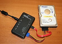
A portable Tableau write-blocker attached to a Hard Drive

A digital forensic investigation commonly consists of 3 stages; acquisition or imaging of exhibits, analysis and reporting.[6][23] Acquisition involves creating an exact sector level duplicate (or "forensic duplicate") of the media, often using a write blocking device to prevent modification of the original. Both acquired image and original media are hashed (using SHA-1 or MD5) and the values compared to verify the copy is accurate.[24]

During the analysis phase an investigators recover evidence material using a number of different methodologies and tools. In 2002 and article in the International Journal of Digital Evidence referred to this step as "an in-depth systematic search of evidence related to the suspected crime".[1] In 2006, forensics researcher Brian Carrie described an "intuitive procedure" in which obvious evidence is first identified and then "exhaustive searches are conducted to start filling in the holes."[4]

The actual process of analysis can vary between investigations, but common methodologies include conducting keyword searches across the digital media (within files as well as unallocated and slack space), recovering deleted files and extraction of registry information (for example to list user accounts, or attached USB devices).

Once evidence is recovered it is analysed to reconstruct events or actions and to reach conclusions, work that can often be performed by less specialist staff.[1] When an investigation is complete the data is presented, usually in the form of a written report, in lay persons terms.[1]

Forms and uses

An example of an image's Exif metadata that might be used to prove its origin

Investigations can take one of four forms. Firstly as a forensic examination, traditionally associated with criminal law, where evidence is collected to support or oppose a hypothesis. Like other areas of forensics this is often part of a wider investigation spanning a number of disciplines. A related form is "intelligence gathering", functionally identical to a forensic examination the digital evidence is intended to be used as intelligence to (for example) locate, identify or halt other crimes. As a result intelligence gathering is sometimes held to a less strict forensic standard.

In civil litigation or corporate matters the process is referred to as electronic discovery (or eDiscovery). The forensic procedure is similar to that used in criminal investigations but with different legal requirements and limitations. Finally, intrusion investigation is a specialist examination into the nature and extent of an unauthorized network intrusion. Intrusion analysis is usually performed as a damage limitation exercise after an attack, both to establish the extent of any intrusion and to try and identify the attacker.[4][3] Such attacks were commonly conducted over phone lines during the 1980s, but in the modern era are usually propagated over the internet.[25]

The main use of digital forensics is to recover objective evidence of a criminal activity (termed actus reus in legal parlance). However the diverse range of data held in digital devices can help with other areas of investigation.[3]

Attribution
Meta data and other logs can be used to attribute actions to an individual. For example, personal documents on a computer drive might identify its owner.
Alibis and statements
Information provided by those involved can be cross checked with digital evidence. For example, during the investigation into the Soham murders, the offenders alibi was disproven when mobile phone records of the person he claimed to be with showed she was out of town at the time.
Intent
As well as finding objective evidence of a crime being committed, investigations can also be used to prove the intent (known by the legal term mens rea). For example, the Internet history of convicted killer Neil Entwistle included references to a site discussing How to kill people.
Evaluation of source
File artifacts and meta-data can be used to identify the origin of a particular piece of data; for example, older versions of Microsoft Word embedded a Global Unique Identifer into files which identified the computer it had been created on. Proving whether a file was produced on the digital device being examined or obtained from elsewhere (e.g., the Internet) can be very important.[3]
Document authentication
Related to "Evaluation of Source", meta data associated with digital documents can be easily modified (for example, by changing the computer clock you can affect the creation date of a file). Document authentication relates to detecting and identifying falsification of such details.

Limitations

One major limitation to a forensic investigation is the use of encryption; this disrupts initial examination where pertinent evidence might be located using keywords. Laws to compel individuals to disclose encryption keys are still relatively new and controversial.[11]

Legal considerations

The examination of digital media is covered by national and international legislation. For civil investigations, in particular, laws may restrict the abilities of analysts to undertake examinations. Restrictions against network monitoring, or reading of personal communications often exist.[26] For criminal investigation, national laws restrict how much information can be seized.[26] For example, in the United Kingdom seizure of evidence by law enforcement is governed by the PACE act.[6] The "International Organization on Computer Evidence" (IOCE) is one agency that works to establish compatible international standards for the seizure of evidence.[27]

In the UK the same laws covering computer crime can also affect forensic investigators. The 1990 computer misuse act legislates against unauthorised access to computer material; this is a particular concern for civil investigators who have more limitations than law enforcement.

An individuals right to privacy is one area of digital forensics which is still largely undecided by courts. The US Electronic Communications Privacy Act places limitations on the ability of law enforcement or civil investigators to intercept and access evidence. The act makes a distinction between stored communication (e.g. email archives) and transmitted communication (such as VOIP). The latter, being considered more of a privacy invasion, is harder to obtain a warrant for.[6][16] The ECPA also affects the ability of companies to investigate the computers and communications of their employees, an aspect that is still under debate as to the extent to which a company can perform such monitoring.[6]

In Europe Article 5 of the European Convention on Human Rights asserts similar privacy limitations to the ECPA. In addition it also limits the processing and sharing of personal data both within the EU and with external countries. In the UK the ability of law enforcement to conduct digital forensics investigations is legislated by the Regulation of Investigatory Powers Act.[6]

Digital evidence

Digital evidence can come in a number of forms

Where it will be used in a court of law, digital evidence falls under the same legal guidelines as other forms of evidence, courts do not usually require more stringent guidelines.[6][28] In the United States the Federal Rules of Evidence are used to evaluate the admissibility of digital evidence, the United Kingdom PACE and Civil Evidence acts have similar guidelines and many other countries have their own laws. US federal laws restrict seizures to items with only obvious evidential value. This is acknowledged as not always being possible to establish with digital media prior to an examination.[26]

Laws dealing with digital evidence refer to two considerations; integrity and authenticity. Integrity is ensuring that the act of seizing and acquiring digital media does not modify the evidence (either the original or the copy). Authenticity refers to the ability to confirm the integrity of information; for example that the imaged media matches the original evidence.[26] The ease with which digital media can be modified means that documenting the chain of custody from the crime scene, through analysis and, ultimately, to the court, (a form of audit trail) is important to establish the authenticity of evidence.[6]

Attorneys have argued that because digital evidence can theoretically be altered it undermines the reliability of the evidence. US judges are beginning to reject this theory, in the case US v. Bonallo the court ruled that "the fact that it is possible to alter data contained in a computer is plainly insufficient to establish untrustworthiness".[6][29] In the United Kingdom guidelines such as those issued by ACPO are followed to help document the authenticity and integrity of evidence.

Digital investigators, particularly in criminal investigations, have to ensure that conclusions are based upon factual evidence and their own expert knowledge.[6] In the US, for example, Federal Rules of Evidence state that a qualified expert may testify “in the form of an opinion or otherwise” so long as:

(1) the testimony is based upon sufficient facts or data, (2) the testimony is the product of reliable principles and methods, and (3) the witness has applied the principles and methods reliably to the facts of the case.[30]

Many of the sub-branches of digital forensics have their own specific guidelines for handling and investigating evidence. For example, mobile phones are often acquired inside a Faraday shield to stop radio traffic to the device. Or, in the UK forensic examination of computers in criminal matters is subject to ACPO guidelines.[6]

Branches

Digital forensics includes several sub-branches relating to the investigation of various types of devices, media or artefacts.

Computer forensics

The goal of computer forensics is to explain the current state of a digital artifact; such as a computer system, storage medium or electronic document.[31] The discipline usually covers computers, embedded systems (digital devices with rudimentary computing power and onboard memory) and static memory (such as USB pen drives).

Computer forensics can deal with a broad range of information; from logs (such as internet history) through to the actual files on the drive. In 2007 prosecutors used a spreadsheet recovered from the computer of Joseph E. Duncan III to show premeditation and secure the death penalty.[3] Sharon Lopatka's killer was identified in 2006 after email messages from him detailing torture and death fantasies were found on her computer.[6]

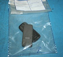
Mobile phones in a UK Evidence bag

Mobile device forensics

Mobile device forensics is a sub-branch of digital forensics relating to recovery of digital evidence or data from a mobile device. It differs from Computer forensics in that a mobile device will have an inbuilt communication system (e.g. GSM) and, usually, proprietary storage mechanisms. Investigations usually focus on simple data such as call data and communications (SMS/Email) rather than in-depth recovery of deleted data.[6][32] SMS data from a mobile device investigation helped to exonerate Patrick Lumumba in the murder of Meredith Kercher.[3]

Mobile devices are also useful for providing location information; either from inbuilt gps/location tracking or via cell site logs (which track the devices within their range). Such information was used to track down the kidnappers of Thomas Onofri in 2006.[3]

Network forensics

Network forensics relates to the monitoring and analysis of computer network (both local network and WAN/internet) traffic for the purposes of information gathering, legal evidence or intrusion detection.[33] Traffic is intercepted (usually at the packet level) and either stored for later analysis with specialist tools or filtered in real time for relevant information. Unlike other areas of digital forensics, network data is often volatile and seldom logged, making the discipline often reactionary.

In 2000, the FBI lured computer hackers Aleksey Ivanov and Gorshkov to the United States for a fake job interview. By monitoring network traffic from the pair's computers, the FBI identified passwords that let it collect evidence directly from Russia-based computers.[6][34]

Database forensics

Database forensics is a branch of digital forensics relating to the forensic study of databases and their metadata.[35] Investigations use database contents, log files and in-RAM data in order to build a time-line or recover relevant information.

See also

Related journals

References

  1. ^ a b c d e f M Reith, C Carr, G Gunsch (2002). "An examination of digital forensic models". International Journal of Digital Evidence. http://citeseerx.ist.psu.edu/viewdoc/summary?doi=10.1.1.13.9683. Retrieved 2 August 2010. 
  2. ^ Carrier, B (2001). "Defining digital forensic examination and analysis tools". Digital Research Workshop II. http://citeseerx.ist.psu.edu/viewdoc/summary?doi=10.1.1.14.8953. Retrieved 2 August 2010. 
  3. ^ a b c d e f g Various (2009). Eoghan Casey. ed. Handbook of Digital Forensics and Investigation. Academic Press. p. 567. ISBN 0123742676. http://books.google.co.uk/books?id=xNjsDprqtUYC. Retrieved 27 August 2010. 
  4. ^ a b c Carrier, Brian D (07). "Basic Digital Forensic Investigation Concepts". http://www.digital-evidence.org/di_basics.html. 
  5. ^ "Florida Computer Crimes Act". http://www.clas.ufl.edu/docs/flcrimes/chapter2_1.html. Retrieved 31 August 2010. 
  6. ^ a b c d e f g h i j k l m n o p q r s t u Casey, Eoghan (2004). Digital Evidence and Computer Crime, Second Edition. Elsevier. ISBN 0-12-163104-4. http://books.google.co.uk/books?id=Xo8GMt_AbQsC. 
  7. ^ Aaron Phillip; David Cowen, Chris Davis (2009). Hacking Exposed: Computer Forensics. McGraw Hill Professional. p. 544. ISBN 0071626778. http://books.google.co.uk/books?id=yMdNrgSBUq0C. Retrieved 27 August 2010. 
  8. ^ a b M, M. E.. "A Brief History of Computer Crime: A". Norwich University. http://www.mekabay.com/overviews/history.pdf. Retrieved 30 August 2010. 
  9. ^ a b Mohay, George M. (2003). Computer and intrusion forensics. Artechhouse. p. 395. ISBN 1580533698. 
  10. ^ a b c Peter Sommer (January 2004). "The future for the policing of cybercrime". Computer Fraud & Security 2004 (1): 8–12. doi:10.1016/S1361-3723(04)00017-X. ISSN 1361-3723. 
  11. ^ a b c Simson L. Garfinkel (August 2010). "Digital forensics research: The next 10 years". Digital Investigation 7: S64-S73. doi:10.1016/j.diin.2010.05.009. ISSN 1742-2876. 
  12. ^ Linda Volonino, Reynaldo Anzaldua (2008). Computer forensics for dummies. For Dummies. pp. 384. ISBN 0470371919. 
  13. ^ GL Palmer, I Scientist, H View (2002). "Forensic analysis in the digital world". International Journal of Digital Evidence. https://utica.edu/academic/institutes/ecii/publications/articles/9C4E938F-E3BE-8D16-45D0BAD68CDBE77.doc. Retrieved 2 August 2010. 
  14. ^ Wilding, E. (1997). Computer Evidence: a Forensic Investigations Handbook. London: Sweet & Maxwell. p. 236. ISBN 0421579900. 
  15. ^ Collier, P.A. and Spaul, B.J. (1992). "A forensic methodology for countering computer crime". Computers and Law (Intellect Books). 
  16. ^ a b K S Rosenblatt (1995). High-Technology Crime: Investigating Cases Involving Computers. KSK Publications. ISBN 0-9648171-0-1. http://www.ncjrs.gov/App/abstractdb/AbstractDBDetails.aspx?id=175264. Retrieved 4 August 2010. 
  17. ^ "Best practices for Computer Forensics". SWGDE. Archived from the original on 3 October 2010. http://www.swgde.org/documents/archived-documents/2004-11-15%20SWGDE%20Best%20Practices%20for%20Computer%20Forensics%20v1.0.pdf. Retrieved 4 August 2010. 
  18. ^ "ISO/IEC 17025:2005". ISO. http://www.iso.org/iso/catalogue_detail.htm?csnumber=39883. Retrieved 20 August 2010. 
  19. ^ SG Punja (2008). "Mobile device analysis". Small Scale Digital Device Forensics Journal. http://www.ssddfj.org/papers/SSDDFJ_V2_1_Punja_Mislan.pdf. 
  20. ^ R Ahmed (2008). "Mobile forensics: an overview, tools, future trends and challenges from law enforcement perspective". 6th International Conference on E-Governance. http://www.iceg.net/2008/books/2/34_312-323.pdf. 
  21. ^ "The Joint Operating Environment", Report released, Feb. 18, 2010, pp. 34–36
  22. ^ Peterson, Gilbert & Shenoi, Sujeet (2009). "Digital Forensic Research: The Good, the Bad and the Unaddressed". Advances in Digital Forensics V (Springer Boston) 306: 17-36. doi:10.1007/978-3-642-04155-6_2. 
  23. ^ "'Electronic Crime Scene Investigation Guide: A Guide for First Responders". National Institute of Justice. 2001. http://www.ncjrs.gov/pdffiles1/nij/187736.pdf. 
  24. ^ Maarten Van Horenbeeck (24). "Technology Crime Investigation". Archived from the original on 17 May 2008. http://web.archive.org/web/20080517022757/http://www.daemon.be/maarten/forensics.html#dr. Retrieved 17 August 2010. 
  25. ^ Warren G. Kruse, Jay G. Heiser (2002). Computer forensics: incident response essentials. Addison-Wesley. p. 392. ISBN 0201707195. 
  26. ^ a b c d Sarah Mocas (February 2004). "Building theoretical underpinnings for digital forensics research". Digital Investigation 1 (1): 61–68. doi:10.1016/j.diin.2003.12.004. ISSN 1742-2876. 
  27. ^ Kanellis, Panagiotis (2006). Digital crime and forensic science in cyberspace. Idea Group Inc (IGI). p. 357. ISBN 1591408733. 
  28. ^ US v. Bonallo, 858 F. 2d 1427 (9th Cir. 1988). Text
  29. ^ "Federal Rules of Evidence #702". http://federalevidence.com/rules-of-evidence#Rule702. Retrieved 23 August 2010. 
  30. ^ A Yasinsac; RF Erbacher, DG Marks, MM Pollitt (2003). "Computer forensics education". IEEE Security & Privacy. http://ieeexplore.ieee.org/iel5/8013/27399/01219052.pdf?arnumber=1219052. Retrieved 26 July 2010. 
  31. ^ "Technology Crime Investigation :: Mobile forensics". Archived from the original on 17 May 2008. http://web.archive.org/web/20080517022757/http://www.daemon.be/maarten/forensics.html#mob. Retrieved 18 August 2010. 
  32. ^ Gary Palmer, A Road Map for Digital Forensic Research, Report from DFRWS 2001, First Digital Forensic Research Workshop, Utica, New York, August 7 – 8, 2001, Page(s) 27–30
  33. ^ "2 Russians Face Hacking Charges". Moscow Times. 24. http://www.themoscowtimes.com/news/article/2-russians-face-hacking-charges/253844.html. Retrieved 3 September 2010. 
  34. ^ Olivier, Martin S. (March 2009). "On metadata context in Database Forensics". Science Direct. doi:10.1016/j.diin.2008.10.001.. http://www.sciencedirect.com/science/article/B7CW4-4TSD9G6-1/2/a5031117d753054d92f2afba332eadf8. Retrieved 2 August 2010. 

Further reading

?

파일시스템
2011.03.19 12:45

hfs+ 개요

조회 수 172635 추천 수 0 댓글 0
?

단축키

Prev이전 문서

Next다음 문서

크게 작게 위로 아래로 댓글로 가기 인쇄 수정 삭제
?

단축키

Prev이전 문서

Next다음 문서

크게 작게 위로 아래로 댓글로 가기 인쇄 수정 삭제

HFS Plus

 
HFS+
Developer Apple
Full name Hierarchical File System Plus
Introduced January 19, 1998 (Mac OS 8.1)
Partition identifier Apple_HFS (Apple Partition Map)
0xAF (MBR)
Apple_HFSX (Apple Partition Map) when HFSX
48465300-0000-11AA-
AA11-00306543ECAC
(GPT)
Structures
Directory contents B-tree
File allocation Bitmap
Bad blocks B-tree
Limits
Max file size 8 EiB[1]
Max number of files 4,294,967,295 (232-1)
Max filename length 255 characters (255 UTF-16 encoding units, normalized to Apple-modified variant of Unicode Normalization Format D)
Max volume size 8 EiB [2]
Allowed characters in filenames Unicode, any character, including NUL. OS APIs may limit some characters for legacy reasons
Features
Dates recorded access, attributes modified, backed up, contents modified, created
Date range January 1, 1904 - February 6, 2040
Date resolution 1 s
Forks Yes
Attributes Color (3 bits, all other flags 1 bit), locked, custom icon, bundle, invisible, alias, system, stationery, inited, no INIT resources, shared, desktop
File system permissions Unix permissions, NFSv4 ACLs (Mac OS X v10.4 onward)
Transparent compression Yes (on Mac OS X 10.6 and higher)
Transparent encryption No, although per-home directory AES using HFS+ formatted .dmg volumes is possible using FileVault in Mac OS X v10.3 onward
Supported operating systems Mac OS 8.1, Mac OS 9, Mac OS X, & Darwin, Linux, Microsoft Windows (through MacDrive or Bootcamp[citation needed] IFS drivers)

HFS Plus or HFS+ is a file system developed by Apple Inc. to replace their Hierarchical File System (HFS) as the primary file system used in Macintosh computers (or other systems running Mac OS). It is also one of the formats used by the iPod digital music player. HFS Plus is also referred to as Mac OS Extended (or, erroneously, “HFS Extended”), where its predecessor, HFS, is also referred to as Mac OS Standard (or, erroneously, as “HFS Standard”). During development, Apple referred to this filesystem with the codename Sequoia.[3]

HFS Plus is an improved version of HFS, supporting much larger files (block addresses are 32-bit length instead of 16-bit) and using Unicode (instead of Mac OS Roman or any of several other character sets) for naming the items (files, folders) – names which are also character encoded in UTF-16[verification needed] and normalized to a form very nearly the same as Unicode Normalization Form D (NFD)[4] (which means that precomposed characters like are decomposed in the HFS+ filename and therefore count as two characters[5] and UTF-16 implies that characters from outside the Basic Multilingual Plane — often seldom used and characters from ancient writing systems — also count as two characters in an HFS+ filename). HFS Plus permits filenames up to 255 UTF-16 characters in length, and n-forked files similar to NTFS, though until recently, almost no software takes advantage of forks other than the data fork and resource fork. HFS Plus also uses a full 32-bit allocation mapping table, rather than HFS’s 16 bits. This was a serious limitation of HFS, meaning that no disk could support more than 65,536 allocation blocks under HFS. When disks were small, this was of little consequence, but as larger-capacity drives became available, it meant that the smallest amount of space that any file could occupy (a single allocation block) became excessively large, wasting significant amounts of space. For example, on a 1 GB disk, the allocation block size under HFS is 16 KB, so even a 1 byte file would take up 16 KB of disk space. Unlike most other file systems HFS Plus supports hard links to directories.

Like HFS, HFS Plus uses B-trees to store most volume metadata.

Contents

[hide]

History

HFS+ was introduced with the January 19, 1998 release of Mac OS 8.1.[1] However its first appearance, as a beta filesystem, was in the never-released Copland OS betas.

With the release of the 10.2.2 update on November 11, 2002, Apple added optional journaling features to HFS Plus for improved data reliability. These features were easily accessible in Mac OS X Server, but only accessible through the command line in the standard desktop client.[6] With Mac OS X v10.3, all HFS Plus volumes on all Macs are set to be journaled by default. Within the system, an HFS Plus volume with a journal is identified as HFSJ.

10.3 also introduced another version of HFS Plus called HFSX. HFSX volumes are almost identical to HFS Plus volumes, except that they are never surrounded by the HFS Wrapper that is typical of HFS Plus volumes and they optionally support case sensitivity for file and folder names. HFSX volumes can be recognized by two entries in the Volume Header, a value of HX in the signature field and 5 in the version field.[1]

Additionally, Mac OS X 10.3 marked Apple's adoption of Unicode 3.2 decomposition, superseding the Unicode 2.1 decomposition used previously. This change has caused problems for developers writing software for Mac OS X.[7]

With 10.4, Apple added support for Inline Attribute Data records, something that had been a part of the Mac OS X implementation of HFS Plus since at least 10.0, but always marked as "reserved for future use".[8] Until the release of Mac OS X Server 10.4, HFS Plus supported only the standard UNIX file system permissions, however 10.4 introduced support for access control list-based file security, which provides a richer mechanism to define file permissions and is also designed to be fully compatible with the file permission models on other platforms such as Microsoft Windows XP and Windows Server 2003.[9]

Design

HFS Plus volumes are divided into sectors (called logical blocks in HFS), that are usually 512 bytes in size. These sectors are then grouped together into allocation blocks which can contain one or more sectors; the number of allocation blocks depends on the total size of the volume. HFS Plus uses a larger value to address allocation blocks than HFS, 32 bits rather than 16 bits; this means it can access 4,294,967,296 (= 232) allocation blocks rather than the 65,536 (= 216) allocation blocks available to HFS.[1]

Formerly, HFS Plus volumes were embedded inside an HFS standard filesystem. This was phased out by the Tiger transition to Intel Macs, where the HFS Plus filesystem was not embedded inside a wrapper. The wrapper was designed for two purposes; it allowed Macintosh computers without HFS Plus support in their ROM to boot HFS Plus volumes and it also was designed to help users transition to HFS Plus by including a minimal HFS volume with a read-only file called Where_have_all_my_files_gone?, explaining to users with versions of Mac OS 8.0 and earlier without HFS Plus, that the volume requires a system with HFS Plus support. The original HFS volume contains a signature and an offset to the embedded HFS Plus volume within its volume header. All allocation blocks in the HFS volume which contain the embedded volume are mapped out of the HFS allocation file as bad blocks.[1]

There are nine structures that make up a typical HFS Plus volume:[1]

  1. Sectors 0 and 1 of the volume are HFS boot blocks. These are identical to the boot blocks in an HFS volume. They are part of the HFS wrapper.
  2. Sector 2 contains the Volume Header equivalent to the Master Directory Block in an HFS volume. The Volume Header stores a wide variety of data about the volume itself, for example the size of allocation blocks, a timestamp that indicates when the volume was created or the location of other volume structures such as the Catalog File or Extent Overflow File. The Volume Header is always located in the same place.
  3. The Allocation File which keeps track of which allocation blocks are free and which are in use. It is similar to the Volume Bitmap in HFS, in which each allocation block is represented by one bit. A zero means the block is free and a one means the block is in use. The main difference with the HFS Volume Bitmap, is that the Allocation File is stored as a regular file, it does not occupy a special reserved space near the beginning of the volume. The Allocation File can also change size and does not have to be stored contiguously within a volume.
  4. The Catalog File is a B-tree that contains records for all the files and directories stored in the volume. The HFS Plus Catalog File is very similar to the HFS Catalog File, the main differences being records are larger to allow more fields and to allow for those fields to be larger (for example to allow the longer 255-character unicode file names in HFS Plus). A record in the HFS Catalog File is 512 bytes in size, a record in the HFS Plus Catalog File is 4 KB in Mac OS and 8 KB in Mac OS X. Fields in HFS are of fixed size, in HFS Plus the size can vary depending on the actual size of the data they store.
  5. The Extents Overflow File is another B-tree that records the allocation blocks that are allocated to each file as extents. Each file record in the Catalog File is capable of recording eight extents for each fork of a file; once those are used extents are recorded in the Extents Overflow File. Bad blocks are also recorded as extents in the Extents Overflow File. The default size of an extent record in Mac OS is 1 KB and 4 KB in Mac OS X.
  6. The Attributes File is a new B-tree in HFS Plus that does not have a corresponding structure in HFS. The Attributes File can store three different types of 4 KB records: Inline Data Attribute records, Fork Data Attribute records and Extension Attribute records. Inline Data Attribute records store small attributes that can fit within the record itself. Fork Data Attribute records contain references to a maximum of eight extents that can hold larger attributes. Extension Attributes are used to extend a Fork Data Attribute record when its eight extent records are already used.
  7. The Startup File is designed for non-Mac OS systems that don't have HFS or HFS Plus support. It is similar to the Boot Blocks of an HFS volume.
  8. The second to last sector contains the Alternate Volume Header equivalent to the Alternate Master Directory Block of HFS.
  9. The last sector in the volume is reserved for use by Apple. It is used during the computer manufacturing process.

Other operating systems

Linux

The Linux kernel includes the hfsplus module[10] for mounting HFS+ filesystems. HFS+ fsck and mkfs have been ported to Linux and are part of the hfsprogs package.[11] These drivers currently have issues with corruption of HFS+ drives with a capacity greater than 2 TB. As such Linux distributions such as Ubuntu do not allow mounting of HFS+ drives or partitions greater than 2 TB.[12]

The Linux HFS+ kernel driver has support to read and write to HFS+ non-journaled drives/parititions but only has read support of journaled HFS+. Journaling ability was added to HFSplus when Mac OS X came out and is by default on for Mac OS X installations. Journaling is a redundant behavior of a filesystem that helps protect data loss. If planning to write to an HFS+ partition then drive journaling must be turned off in OSX.[13]

Windows

On Windows, a fairly complete filesystem driver for HFS+ exists as a commercial software package called MacDrive.[14] This package allows Windows users to read and write HFS+ formatted drives, and read Mac-format optical disks.

Another solution is provided by Paragon, with their HFS+ for Windows driver; this supports both read and write on HFS+ partitions.[15]

Apple has released read-only HFS+ drivers for Windows XP, Windows Vista, and Windows 7 in Boot Camp in Mac OS X 10.6. Microsoft has created a HFS+ driver for the XBox 360 mainly for the purpose of reading HFS+ formatted iPods.

A free (GPL) alternative to MacDrive is HFSExplorer written by Erik Larsson.[16] HFSExplorer is an application for viewing and extracting files from an HFS+ volume (Mac OS Extended) or an HFSX volume (Mac OS Extended, Case-sensitive) located either on a physical disk, on a .dmg disk image, or in a raw file system dump. HFSExplorer is less complete than MacDrive in the sense that it can read, but not write to HFS formatted volumes.

See also

References

  1. ^ a b c d e f "Technical Note TN1150: HFS Plus Volume Format". Apple Developer Connection. March 5, 2004. http://developer.apple.com/technotes/tn/tn1150.html. Retrieved 2007-03-28. 
  2. ^ "Mac OS X: Mac OS Extended format (HFS Plus) volume and file limits". Support.apple.com. 2008-07-29. http://support.apple.com/kb/HT2422. Retrieved 2010-07-05. 
  3. ^ "New Mac OS Extended Format (HFS+) Available". Apple Developer News. 1997. http://developer.apple.com/adcnews/pastissues/devnews090597.html. Retrieved 2007-03-28. 
  4. ^ "Technical Q&A QA1235: Converting to Precomposed Unicode". Apple Developer Connection. February 7, 2003. http://developer.apple.com/qa/qa2001/qa1235.html. Retrieved 2007-03-28. 
  5. ^ there are some minor differences derived from the fact that the HFS Plus format was finalized before Unicode had standardized the NFD format (see “Unicode Subtleties” for more information)
  6. ^ John Gruber (November 11, 2002). "Crow". DaringFireball.net. http://daringfireball.net/2002/11/crow. Retrieved 2007-03-28. 
  7. ^ "Re: git on MacOSX and files with decomposed utf-8 file names". KernelTrap. 2010-05-07. http://kerneltrap.org/mailarchive/git/2008/1/23/593749/thread. Retrieved 2010-07-05. 
  8. ^ John Siracusa (April 28, 2005). "Mac OS X 10.4 Tiger: Metadata revisited". Ars Technica. http://arstechnica.com/reviews/os/macosx-10.4.ars/6. Retrieved 2007-03-28. 
  9. ^ "Apple - Mac OS X Server - Windows Services". Apple.com. Archived from the original on 2007-12-31. http://web.archive.org/web/20071231203318/http://www.apple.com/br/server/macosx/windowsservices.html. Retrieved 2007-11-12. 
  10. ^ Git Repository Kernel.org
  11. ^ User-space supporting tools for HFS+ filesystems under Posix systems.
  12. ^ http://bugs.debian.org/cgi-bin/bugreport.cgi?bug=550010
  13. ^ http://ubuntuforums.org/showthread.php?p=2346494
  14. ^ "MacDrive". Mediafour. http://www.mediafour.com/products/macdrive/. Retrieved 2010-07-05. 
  15. ^ "HFS for Windows - file system driver | PARAGON Software Group". Paragon-software.com. http://www.paragon-software.com/home/hfs-windows/. Retrieved 2010-07-05. 
  16. ^ "Catacombae - HFSExplorer". Erik Larsson. 2008-12-23. http://catacombae.org/hfsx.html. Retrieved 2010-12-19. 

External links

  • Apple Technote 1150 - HFS Plus Volume Format
  • Apple Technote 1189 - The Monster Disk Driver Technote
  • hfsdebug - A debugger for HFS Plus volumes by Amit Singh
  • hfsprogs - Userspace support tools for HFS+ filesystems under Linux systems (adapted from Apple's native tools).
  • iBored - A disk editor and viewer supporting HFS Plus


?

파일시스템
2011.03.19 12:43

ext2 개요

조회 수 6030 추천 수 0 댓글 0
?

단축키

Prev이전 문서

Next다음 문서

크게 작게 위로 아래로 댓글로 가기 인쇄 수정 삭제
?

단축키

Prev이전 문서

Next다음 문서

크게 작게 위로 아래로 댓글로 가기 인쇄 수정 삭제

ext

Developer Rémy Card
Full name Second extended file system
Introduced January 1993 (Linux)
Partition identifier Apple_UNIX_SVR2 (Apple Partition Map)
0x83 (Master Boot Record)
EBD0A0A2-B9E5-4433-87C0-68B6B72699C7 (GPT)
Structures
File allocation bitmap (free space), table (metadata)
Bad blocks Table
Limits
Max file size 16 GB - 2 TB
Max number of files 1018
Max filename length 255 bytes
Max volume size 2-32 TB
Allowed characters in filenames Any byte except NUL and '/'
Features
Dates recorded modification (mtime), attribute modification (ctime), access (atime)
Date range December 14, 1901 - January 18, 2038
Date resolution 1s
File system permissions POSIX
Transparent compression No (Available through patches)
Transparent encryption No
Supported operating systems Linux, BSD, Windows (through an IFS), Mac OS X (through an IFS)

The ext2 or second extended filesystem is a file system for the Linux kernel. It was initially designed by Rémy Card as a replacement for the extended file system (ext).

The canonical implementation of ext2 is the ext2fs filesystem driver in the Linux kernel. Other implementations (of varying quality and completeness) exist in GNU Hurd, MINIX 3, Mac OS X (third-party), Darwin (same third-party as Mac OS X but untested), some BSD kernels, in Atari MiNT, and as third-party Microsoft Windows drivers.

ext2 was the default filesystem in several Linux distributions, including Debian and Red Hat Linux, until supplanted more recently by ext3, which is almost completely compatible with ext2 and is a journaling file system. ext2 is still the filesystem of choice for flash-based storage media (such as SD cards, and USB flash drives) since its lack of a journal minimizes the number of writes and flash devices have only a limited number of write cycles. Recent kernels, however, support a journal-less mode of ext4, which would offer the same benefit along with a number of ext4-specific benefits.

Contents

[hide]

History

The early development of the Linux kernel was made as a cross-development under the Minix operating system. Naturally, it was obvious that the Minix file system would be used as Linux's first file system. The Minix file system was mostly free of bugs, but used 16-bit offsets internally and thus only had a maximum size limit of 64 megabytes. There was also a filename length limit of 14 characters. Because of these limitations, work began on a replacement native file system for Linux.

To ease the addition of new file systems and provide a generic file API, VFS, a virtual file system layer was added to the Linux kernel. The extended file system (ext), was released in April 1992 as the first file system using the VFS API and was included in Linux version 0.96c. The ext file system solved the two major problems in the Minix file system (maximum partition size and filename length limitation to 14 characters), and allowed 2 gigabytes of data and filenames of up to 255 characters. But it still had problems: there was no support for separate access, inode modification and data modification timestamps.

As a solution for these problems, two new filesystems were developed in January 1993: xiafs and the second extended file system (ext2), which was an overhaul of the extended file system incorporating many ideas from the Berkeley Fast File System. ext2 was also designed with extensibility in mind, with space left in many of its on-disk data structures for use by future versions.

Since then, ext2 has been a testbed for many of the new extensions to the VFS API. Features such as POSIX ACLs and extended attributes were generally implemented first on ext2 because it was relatively simple to extend and its internals were well-understood.

On Linux kernels prior to 2.6.17,[1] restrictions in the block driver mean that ext2 filesystems have a maximum file size of 2TB.

ext2 is still recommended over journaling file systems on bootable USB flash drives and other solid-state drives. ext2 performs fewer writes than ext3 since it does not need to write to the journal. As the major aging factor of a flash chip is the number of erase cycles, and as those happen frequently on writes, this increases the life span of the solid-state device.[2] Another good practice for filesystems on flash devices is the use of the noatime mount option, for the same reason.

ext2 data structures

The space in ext2 is split up into blocks. These blocks are divided into block groups, analogous to cylinder groups in the Unix File System. There are typically thousands of blocks on a large file system. Data for any given file is typically contained within a single block group where possible. This is done to reduce external fragmentation and minimize the number of disk seeks when reading a large amount of consecutive data.

Each block group contains a copy of the superblock and block group descriptor table, and all block groups contain a block bitmap, an inode bitmap, an inode table and finally the actual data blocks.

The superblock contains important information that is crucial to the booting of the operating system, thus backup copies are made in multiple block groups in the file system. However, typically only the first copy of it, which is found at the first block of the file system, is used in the booting.

The group descriptor stores the location of the block bitmap, inode bitmap and the start of the inode table for every block group and these, in turn are stored in a group descriptor table.

Inodes

Every file or directory is represented by an inode. The inode includes data about the size, permission, ownership, and location on disk of the file or directory.

Example of ext2 inode structure:

Estructure

Quote from the linux kernel documentation for ext2:

"There are pointers to the first 12 blocks which contain the file's data in the inode. There is a pointer to an indirect block (which contains pointers to the next set of blocks), a pointer to a doubly-indirect block (which contains pointers to indirect blocks) and a pointer to a trebly-indirect block (which contains pointers to doubly-indirect blocks)."

So, there is a structure in ext2 that has 15 pointers, the first 12 are for direct blocks. Pointer number 13 points to an indirect block, number 14 to a doubly-indirect block and number 15 to a trebly-indirect block.

Directories

Each directory is a list of directory entries. Each directory entry associates one file name with one inode number, and consists of the inode number, the length of the file name, and the actual text of the file name. To find a file, the directory is searched front-to-back for the associated filename. For reasonable directory sizes, this is fine. But for huge large directories this is inefficient, and ext3 offers a second way of storing directories that is more efficient than just a list of filenames.

The root directory is always stored in inode number two, so that the file system code can find it at mount time. Subdirectories are implemented by storing the name of the subdirectory in the name field, and the inode number of the subdirectory in the inode field. Hard links are implemented by storing the same inode number with more than one file name. Accessing the file by either name results in the same inode number, and therefore the same data.

The special directories "." and ".." are implemented by storing the names "." and ".." in the directory, and the inode number of the current and parent directories in the inode field. The only special treatment these two entries receive is that they are automatically created when any new directory is made, and they cannot be deleted.

Allocating Data

When a new file or directory is created, the EXT2 file system must decide where to store the data. If the disk is mostly empty, then data can be stored almost anywhere. However, performance is maximized if the data is clustered with other related data to minimize seek times.

The EXT2 file system attempts to allocate each new directory in the group containing its parent directory, on the theory that accesses to parent and children directories are likely to be closely related. The EXT2 file system also attempts to place files in the same group as their directory entries, because directory accesses often lead to file accesses. However, if the group is full, then the new file or new directory is placed in some other non-full group.

The data blocks needed to store directories and files can found by looking in the data allocation bitmap. Any needed space in the inode table can be found by looking in the inode allocation bitmap.

File system limits

Theoretical ext2 filesystem limits under Linux[3]
Block size: 1 KB 2 KB 4 KB 8 KB
max. file size: 16 GB 256 GB 2 TB 2 TB
max. filesystem size: 4* TB 8 TB 16 TB 32 TB

The reason for some limits of the ext2-file system are the file format of the data and the operating system's kernel. Mostly these factors will be determined once when the file system is built. They depend on the block size and the ratio of the number of blocks and inodes. In Linux the block size is limited by the architecture page size.

There are also some userspace programs that can't handle files larger than 2 GB.

The maximum file size is limited to min( ((b/4)3+(b/4)2+b/4+12)*b, 232*b ) due to the i_block (an array of EXT2_N_BLOCKS) and i_blocks( 32-bits integer value ) representing the amount of b-bytes "blocks" in the file.

The limit of sublevel-directories is 31998 due to the link count limit. Directory indexing is not available in ext2, so there are performance issues for directories with a large number of files (10,000+). The theoretical limit on the number of files in a directory is 1.3 × 10²⁰, although this is not relevant for practical situations.

Note: In Linux kernel 2.4 and earlier block devices were limited to 2 TB, limiting the maximum size of a partition regardless of block size.

Compression extension

e2compr is a modification to the ext2 file system driver in the Linux kernel to support online compression and decompression of files on file system level without any support by user applications.

e2compr is a small patch against the ext2 file system that allows on-the-fly compression and decompression. It compresses only regular files; the administrative data (superblock, inodes, directory files etc.) are not compressed (mainly for safety reasons). Access to compressed blocks is provided for read and write operations. The compression algorithm and cluster size is specified on a per-file basis. Directories can also be marked for compression, in which case every newly created file in the directory will be automatically compressed with the same cluster size and the same algorithm that was specified for the directory.

e2compr is not a new file system. It is only a patch to the ext2 file system made to support the EXT2_COMPR_FL flag. It does not require you to make a new partition, and will continue to read or write existing ext2 file systems. One can consider it as simply a way for the read and write routines to access files that could have been created by a simple utility similar to gzip or compress. Compressed and uncompressed files coexist nicely on ext2 partitions.

The latest e2compr-branch is available for current releases of 2.6 and 2.4 Linux kernels, but development is stalled. There are also older branches for older 2.0 and 2.2 kernels, which are more stable.

See also

References

  1. ^ linux/kernel/git/torvalds/linux-2.6.git/commitdiff:, [PATCH] 2TB files: add blkcnt_t, Author:Takashi Sato, 26 Mar 2006 09:37:52 +0000 (01:37 -0800) — Commit allowing for large files, git.kernel.org
  2. ^ "Solid State Disk Drives". Super Talent Technology. http://www.supertalent.com/tools/ssd.php. 
  3. ^ "File system guide". Linux Reviews. http://linuxreviews.org/sysadmin/filesystems/. 
Notes

Further reading

External links

?

파일시스템
2011.03.19 12:30

EXT3 개요

조회 수 2548 추천 수 0 댓글 0
?

단축키

Prev이전 문서

Next다음 문서

크게 작게 위로 아래로 댓글로 가기 인쇄 수정 삭제
?

단축키

Prev이전 문서

Next다음 문서

크게 작게 위로 아래로 댓글로 가기 인쇄 수정 삭제

ext3

ext3(extended file system 3, 확장된 파일 시스템 3)는 파일 시스템 가운데 하나로 만든 이는 스테펜 트위디(Stephen Tweedie)이다. 2001년 11월 리눅스 커널 2.4.15판에서 처음 모습을 드러냈으며 오늘날 많은 리눅스 커널 기반 운영 체제에서 주 파일 시스템으로 쓰이고 있다.


장점

  • ext2에서 자료 삭제 및 손실 없이 ext3으로 변경할 수 있다(자료를 백업할 필요가 없음).
  • 저널링
  • 온라인 파일 시스템 증대
  • 큰 규모의 디렉터리를 위한 Htree(btree의 고급판)

이 밖의 모든 것들은 ext2와 같다. ext2를 유지하고 복구하기 위해 충분한 테스트를 거쳐 보다 완전해진 파일 시스템 유지보수 유틸리티들을 포함하여 ext2 파일 시스템에서 큰 변화 없이 ext3와 함께 사용될 수 있도록 하였다. ext2와 ext3 둘 다 e2fsprogs를 사용하며 이 유틸리티는 fsck를 포함하고 있다. 이러한 밀접한 관련으로 이 두 파일 시스템들은 상호 변환이 용이하다.

저널링

Ext3를 지원하는 리눅스 시스템에서는 다음과 같은 3단계 저널링을 사용할 수 있다.

  • Journal (리스크 최소)

두 파일 시스템의 메타 데이터와 파일 컨텐츠는 메인 파일 시스템에 전달되기 전에 저널에 기록된다. 저널은 비교적 디스크와 관련이 있어서 어떤 경우에는 성능을 향상시킬 수 있으나, 데이터가 저널에 한 번, 파일 시스템에 한 번, 이렇게 두 번 기록되기 때문에 성능이 저하될 수도 있다.

  • Ordered (리스크 중간)

메타 데이터만 저널에 기록된다. 파일 컨텐츠는 기록되지는 않지만 만일 관련된 메타 데이터가 저널에 기록되면 파일 컨텐츠는 디스크에 반드시 기록된다. 이는 많은 리눅스 배포판에 기본 설정으로 되어 있다. 만일 파일을 읽거나 쓰는 도중에 전원이 갑자기 꺼지거나 커널 패닉 상태가 되면, 저널은 새로운 파일을 가리키게 되거나 추가된 데이터가 넘겨지지 않으며, 삭제 처리된다. 하지만, 중복 쓰기가 된 파일은 원본이 저장되지 않아 파일이 손상될 수 있는데, 파일을 복구하기 위한 충분한 정보 없이 새 파일과 이전 파일의 중간 상태에서 파일이 종료될 수 있다. - 새로운 데이터는 완벽하게 디스크에 저장되지 않으며, 이전 데이터는 어디에도 저장되지 않는다. - 심한 경우에는, 중간 상태가 이전 데이터와 새 데이터 사이에 혼란을 줄 수 있다.[1][2]

  • Writeback (리스크 최고)

메타 데이터만 저널에 기록되며, 파일의 내용은 기록되지 않는다. 파일 내용은 저널이 업데이트된 후에나 아니면 그 이전에 기록될 수 있으며, 결과적으로 충돌 바로 전에 수정된 파일들은 손상될 수 있다. 예를 들어, 추가된 파일이 실제 크기보다 더 큰 파일로 저널에 기록되면, 결국은 "쓰레기(의미 없는 정보)"를 만들게 된다. 오래된 파일일수록 저널이 복구된 후에 예상치 못한 결과가 나타날 수 있다. 데이터와 저널 사이에 동시성이 결여되며 대부분의 경우에서 점점 심해진다. XFS와 JFS는 이러한 저널링 레벨을 사용하지만 데이터를 기록하지 않기 때문에 모든 "쓰레기"는 재부팅 시 완전히 삭제된다.

일부 상황에서는 동적 inode 할당 및 확장과 같은 현대 파일시스템의 기능 부족이 단점으로 여겨질 수 있지만, 복구의 측면에서는 이러한 사실이 아주 뛰어난 장점이 된다. 파일 시스템의 메타 데이터는 모두 수정되고, 잘 알려진 위치에 존재하며, 데이터 구조에 일부 중복성이 내재되어 있어, 트리 기반의 파일 시스템이 복구되기 어려운 상황에서도 뚜렷한 데이터 손상에도 불구하고 ext2 및 ext3 파일시스템이 복구될 수 있다.

단점

  • 기능 (Functionality)

ext3는 ext2와 대부분 호환이 가능하도록 하는 것을 목표로 하였고, 많은 on-disk 구조들이 ext2의 on-disk와 비슷하다. 이 때문에, ext3는 inode의 동적 할당 및 다양한 블록 크기(frag와 tail)와 같은 최신 파일시스템 설계의 기능들이 부족하다. ext3 파일 시스템은 쓰기를 위해 마운트 되어있는 동안에는 fsck를 할 수 없다. 읽기-쓰기가 마운트 되어있는 동안 수집된 파일 시스템의 덤프 작업은 데이터 손상을 가져올 수 있다.

ext3는 JFS, ext4, 그리고 XFS와 같은 다른 파일 시스템에서 볼 수 있는 기능인 extents 기능을 지원하지 않는다.

  • 조각 모음 (Defragmentation)

파일 시스템 레벨에서 사용할 수 있는 온라인 ext3 조각 모음 기능은 없다. e2defrag라고 하는 오프라인 ext2 조각 모음기가 있지만 ext3 파일 시스템은 ext2로 먼저 재변환되어야 한다. e2defrag는 데이터를 손상시킬 수 있다. 왜냐하면 e2defrag는 ext3의 새로운 기능들을 어떻게 다루어야 하는지 잘 알지 못하기 때문이다.[3]

사용자 공간에서 이용할 수 있는 defragmentation 도구에는 Shake[4]와 defrag[5] 등이 있다. Shake는 전체 파일을 위한 공간을 바로 할당하며 단편화가 많이 되지 않도록 새롭게 파일을 할당하는 역할을 한다. 또한, 다음에 같이 사용되는 파일을 서로 쓸 수 있도록 한다. Defrag는 각 파일 스스로가 복사할 수 있도록 한다. 하지만 이러한 도구들은 파일 시스템이 비어 있을 때만 작동한다. 실제 조각 모음 도구는 ext3를 위해 존재하는 것이 아니다. [6] 'Linux System Administrator Guide' 에서는 "현재의 리눅스 파일 시스템은 연속적인 섹터에 저장될 수 없음에도 불구하고 서로가 파일 상에서 근접하게 모든 블록을 최소한으로 유지함으로써 단편화를 허용한다. 따라서 리눅스 시스템에서 단편화를 걱정할 필요는 없다." 라고 기술되어 있다.[7]

전술한 것과는 상관 없이, 파일 단편화는 멀티미디어 서버 응용 프로그램에서와 같은 서버 환경에서는 매우 중요한 문제가 될 수 있다. ext3는 FAT 파일 시스템보다는 파일 단편화에 강한 편이지만 그럼에도 불구하고 ext3 파일 시스템은 시간이 지날수록 단편화가 더욱 진행된다. 결과적으로 ext3의 다음 버전인 ext4의 경우 파일 시스템 조각 모음 유틸리티를 포함하며 extents 또한 지원하게 된다. 속도가 빠르고, 동시적이며 랜덤한 파일 생성, 업데이트 및 접근이 일어나는 곳에서의 서버 응용 프로그램들은, (ext3와 같은) 일부 리눅스 파일 시스템에 조각 모음 기능이 없어서 큰 문제가 되기도 한다. 이러한 시스템에는 큰 규모의 carrier grade 음성 메일 시스템을 포함, Media-Messaging Service Centers(MMSCs) 및 SMS/SMSC(Short Message Service Centers) 서버도 포함된다. 규모가 큰 음성 메일과 같은 미디어 서버나 UMS 서버는 거의 실시간 상태로 수많은 사용자에게 음성 및 영상 스트림을 연결해주어야 한다. 이러한 타입의 응용 프로그램들은 파일 단편화가 이루어질 가능성이 있다. 음성이나 영상 파일을 재생하는 동안 미디어 파일 내에 많은 단편화 현상 때문에 접근 지연으로 재생 불능이나 재생 방해가 발생할 수 있다. 단편화 현상이 증가함에 따라, CPU 및 I/O 오버헤드 증가로 디스크 thrashing을 일으켰던 단편화를 가져오게 됨으로써 이러한 시스템들의 서비스 능력이 떨어지게 된다.

  • 압축 (Compression)

ext3의 비공식 패치에서는 투명 압축이 지원된다. 이 패치는 e2compr의 직접적인 포트이며 개발이 더 필요한 상태이며, 업스트림 커널과 컴파일 및 부팅이 잘 되지만 저널링은 아직 구현되지 않았다. 현재 패치는 e3compr이며 다음 링크에서 확인할 수 있다: http://sourceforge.net/projects/e3compr/

  • 크기 제한 (Size limits)

ext3는 개별 파일 및 전체 파일 시스템 상의 최대 크기에 제한을 두고 있다. 이러한 제한은 파일 시스템의 블록 사이즈에 따라 결정된다.[8] (다음 차트 참조)

제한 크기
블록 크기 파일 최대 크기 파일 시스템 최대 크기
1KiB 16GiB 2TiB
2KiB 256GiB 8TiB
4KiB 2TiB 16TiB
8KiB 2TiB 32TiB

참고 8KiB 블록 사이즈는 8KiB 페이지(Alpha와 같은)를 허용하는 아키텍처에서만 가능하다. [영문 ext3 wiki] 여기와 내용이 틀림.

  • Checksum을 검사하지 않는다. (No checksumming in journal)

Ext3는 저널에 기록할 때 checksum 검사를 하지 않는다. ‘barrier=1’이 마운트 옵션 (/etc/fstab)으로써 활성화되지 않고, 하드웨어가 캐시에 기록이 되지 않을 때, 충돌이 일어나는 동안 심각한 파일 시스템 손상의 위험을 일으킨다.[9][10] (이 옵션은 대부분 모든 유명한 리눅스 배포판에는 기본적으로 비활성화 상태로 되어 있는데 이것은 대부분의 리눅스 배포판들이 이러한 위험에 노출되어 있다는 것을 의미한다.) 다음과 같은 시나리오를 생각해 볼 수 있다. 하드 디스크 쓰기가 제대로 작동하지 않는다면 (쓰기 속도를 향상시키기 위한 하드 디스크 캐싱 때문에), 하드 디스크는 다른 관련된 블록에 쓰기가 실행되기 전에 하나의 트랜잭션의 commit 블록을 종종 쓰게 된다. 다른 블록들에 쓰기가 되기 전에 전원이 잘못되거나 커널 패닉이 발생하면, 시스템은 재부팅을 해야만 하는 상태가 된다. 리부팅 시, 파일 시스템은 정상적으로 로그를 읽어 들여와서, winners (유효한 commit 블록과 함께 표시되도록 했던 유효하지 않은 트랜잭션을 포함하여 commit 블록이 있는 트랜잭션)를 재실행한다. 종료되지 않은 디스크 쓰기는 결과적으로 진행될 것이지만 손상된 저널 데이터를 사용하게 된다. 파일 시스템은 저널을 재실행하는 동안 손상된 데이터와 함께 정상적인 데이터의 중복 쓰기를 실행한다. 만일 checksum이 사용되었더라면 (상호 checksum으로 fake winner 트랜잭션의 블록이 표시가 된다면), 파일 시스템은 보다 더 잘 알게 되고 디스크 상에서 손상된 데이터를 다시 실행할 필요가 없다.

명세

Ext3
개발자 Stephen Tweedie
이름 Third Extended File System
배포 2001년 11월 (Linux 2.4.15)
파티션 식별자 0x83 (MBR) EBD0A0A2-B9E5-4433-87C0-68B6B72699C7 (GPT)
구조
디렉터리 내용 Table, h-Tree, dir_index
파일 할당 bitmap (free space), table (metadata)
배드 블록 Table
제한
최대 파일 크기 16GiB – 2TiB
최대 파일 개수 파일 시스템 생성 시 다양하게 지정 가능[11]
최대 파일 이름 길이 255 바이트
최대 볼륨 크기 2TiB – 32TiB
파일 이름 허용 문자 NUL 및 ‘/’를 제외한 모든 바이트 단위 문자
특징
기록 날짜 수정 (mtime), 속성 수정 (ctime), 접근 (atime)
날짜 표현 범위 1901년 12월 14일 - 2038년 1월 18일
날짜 표현 단위 1s
Forks
속성 No-atime, append-only, synchronous-write, no-dump, h-tree (directory),

immutable, journal, secure-delete, top (directory), allow-undelete

파일 시스템 권한 Unix 권한, ACLs 및 임의의 보안 속성 (Linux 2.6 이후 버전)
투명 압축 지원 안함
투명 암호와 지원 안함 (블록 장치 레벨에서 제공됨)
지원 OS Linux, BSD, Windows (IFS를 통해 지원)

같이 보기

주석

  1. curious onloooker: Speeding up ext3 filesystems
  2. Common threads: Advanced filesystem implementor's guide, Part 8
  3. Andreas Dilger. Post to the ext3-users mailing list. ext3-users mailing list post.
  4. Vleu.net: Shake
  5. Index of /apps/defrag
  6. RE: searching for ext3 defrag/file move program
  7. http://www.tldp.org/LDP/sag/html/filesystems.html
  8. Matthew Wilcox. Documentation/filesystems/ext2.txt. Linux kernel source documentation.
  9. Re: Frequent metadata corruption with ext3 + hard power-off
  10. Re: Frequent metadata corruption with ext3 + hard power-off
  11. inode의 최대 개수는 파일 시스템 생성시 결정된다 (즉, 파일 및 디렉터리의 최대 개수). V는 바이트 단위의 볼륨 사이즈를 말하며, inode의 디폴트 개수는 V/213이고 (또는 블록의 개수, 어느 것이든 해당 개수보다 작다), V/223가 최소값이다. 디폴트 값은 대부분의 응용 프로그램에서 충분한 값이다. 한 디렉터리가 포함하는 하위 디렉터리의 최대 개수는 32000으로 고정된다.

바깥 고리


?

파일시스템
2011.03.17 16:10

파일시스템의 정의

조회 수 1721 추천 수 0 댓글 0
?

단축키

Prev이전 문서

Next다음 문서

크게 작게 위로 아래로 댓글로 가기 인쇄 수정 삭제
?

단축키

Prev이전 문서

Next다음 문서

크게 작게 위로 아래로 댓글로 가기 인쇄 수정 삭제

파일 시스템

파일 시스템(file system, 파일체계)은 컴퓨터에서 파일이나 자료를 쉽게 발견 및 접근할 수 있도록 보관 또는 조직하는 체제를 가리키는 말이다.

파일 시스템은 통상 하드 디스크CD-ROM 같은 실제 자료 보관 장치를 사용하여 파일의 물리적 소재를 관리하는 것을 가리키나 네트워크 프로토콜(NFS, SMB, 9P 등)을 수행하는 클라이언트를 통하여 파일 서버 상의 자료로의 접근을 제공하는 방식과 가상의 형태로서 접근 수단만이 존재하는 방식(procfs 등)도 파일 시스템의 범위에 포함될 수 있다. 디렉터리 서비스레지스트리와는 의미가 조금 다르다.


구성

하드 디스크 내장 / 파티션 모형

개요

파일 시스템은 일반적으로 크기가 일정한 블록들의 배열(섹터라고도 불리며 통상 512바이트, 1키비바이트, 2키비바이트같은 - 2를 제곱한 수만큼의 크기를 갖는다)에 접근할 수 있는 자료 보관 장치 위에 생성되어 이러한 배열들을 조직함으로 파일이나 디렉터리를 만들며 어느 부분이 파일이고 어느 부분이 공백인지를 구분하기 위하여 각 배열에 표시를 해 둔다. 또한 자료를 '클러스터' 또는 '블록'이라고 불리는 일정한 단위(이것은 각 디스크 배열들에 대한 식별할 수 있는 번호를 제공하는데 통상 1부터 64까지가 쓰인다)에 새겨 넣는데 이것이 바로 파일 하나가 필요로 하는 디스크의 최소 공간이다.

파일 이름

파일에 이름이 존재함은 컴퓨터 메모리 안에서 해당 파일의 소재 위치를 보장하기 위함이다. 파일 시스템 안에서 디렉터리는 통상 파일 이름과 해당 파일을 연결해 주는데 도스FAT유닉스 계열 운영 체제아이노드의 경우 파일 이름을 색인과 연결한다. 디렉터리 구조는 수평형일 수도 있고 수직형(하위 디렉터리 있음)일 수도 있다. 어떤 파일 시스템에서는 파일 이름이 이름, 확장자, 판 수 이런 식으로 특별한 문법을 따르기도 하며 또 어떤 파일 시스템에서는 파일 이름은 그저 문자열 정도로만 취급되고 각 파일마다 어딘가에 메타데이터가 보관된다.

계층

일반적으로 파일 시스템은 '저장 장치 - 입출력 제어 - 기본 파일시스템 - 파일조직 모듈 - 가상 파일시스템'과 같이 여러 개의 계층으로 구성되어 있다. 그렇게 함으로써 하드 디스크, 시디롬 드라이브, 플래시 메모리 등 다양한 형태의 저장 장치를 지원할 수 있고, 하나의 시스템에 여러 개의 파일 시스템을 사용하는 것이 가능해진다.

파일 시스템의 종류

파일 시스템은 크게 디스크, 네트워크, 그리고 특수 용도의 파일 시스템으로 나눌 수 있다.

디스크 파일 시스템

자료 기억 장치, 특히 컴퓨터에 연결된 디스크 드라이브에 파일을 저장하도록 설계된 시스템이다.

보기

데이터베이스 파일 시스템

데이터베이스 기반의 파일 시스템은 최근에 등장한 새로운 개념의 파일 시스템이다. 파일을 계층 구조로 관리하지 않고 파일의 형식, 주제, 만든이, 내용과 같은 여러 특성에 따라 시스템에서 자동으로 분류하여 관리하는 것이다. 따라서 쿼리 언어나 자연어 등으로 파일을 빠르게 찾을 수 있다.

보기

트랜잭션 기반 파일 시스템

트랜잭션 기반 파일 시스템은 파일에 일어난 이벤트나 트랜잭션을 기록하는 시스템이다. 사용자가 수행하는 작업은 여러 개의 파일의 내용을 바꿀 수 있다. 이 바뀐 내용들은 서로 연관되어 있는 경우가 많으므로 이 내용들이 논리적으로 서로 연결되어 있어야 하는 시스템에서는 이 변화들이 동시에 일어난다는 것이 보장되어야 한다. 은행 계좌에서 돈을 이체하는 경우를 예로 들어 보자. 당신이 온라인으로 돈을 이체할 때 은행 컴퓨터는 상대방의 은행 컴퓨터에 "전송" 명령을 보내고 동시에 당신의 계좌에서 같은 금액을 줄일 것이다. 그런데 이때 시스템에 우연히 사고가 일어나 전송 명령이 보내지지 않았다면 상대방의 계좌에 돈은 입금되지 않았는데 당신의 계좌에서는 돈이 사라지는 일이 일어날 수 있다. 트랜잭션 기반 시스템은 이렇게 논리적으로 동시에 수행되어야 하는 작업들을 하나의 "트랜잭션"으로 묶어 만약의 사고가 일어났을 때 양쪽에서 트랜잭션을 다시 수행하여 오류를 막는다. 또한 모든 트랜잭션은 기록으로 남아 어디서 무슨 일이 언제 수행되었는지가 기록된다. 이러한 파일 시스템은 시스템의 오류를 막기 위해 설계되었으며, 느리지만 안전하다고 볼 수 있다.

특수 용도의 파일 시스템

유닉스와 같은 파일 중심의 운영 체제는 여러 가지 특수 용도의 파일 시스템을 사용한다. 예를 들면, 어떤 종류의 유닉스는 '/proc'이라는 파일 시스템에서 프로세스나 운영 체제 여러 기능에 접근할 수 있다.

심우주 탐사선인 보이저 1호2호에는 디지털 테이프 기반의 파일 시스템이 탑재되어 있다. 카시니-하위헌스 호와 같은 현대 우주선들은 실시간 운영 체제를 위한 파일 시스템을 탑재한다. 화성 탐사선들도 실시간 운영 체제를 탑재하고 있는데, 이들의 파일 시스템은 플래시 메모리를 사용한다.

파일 시스템과 운영 체제

대부분의 운영 체제는 파일 시스템을 갖고 있으며, 파일은 현대의 모든 운영 체제의 기본 구성 요소이다. 마이크로컴퓨터의 초창기 운영 체제 도스(곧, 디스크 운영 체제)의 주 목적은 파일 관리였다. 이러한 초창기 운영 체제들은 디스크를 관리하는 시스템을 따로 설계했다. 이러한 운영 체제들은 내부에 단 하나의 파일 시스템만을 지원했다.

유닉스 계열의 파일 시스템

유닉스나 다른 유닉스 계열 운영 체제들은 여러 개의 주변 장치에 각각의 이름을 붙이지만, 그 주변 장치에 존재하는 파일들은 전부 하나의 계층 구조 아래 관리된다. 다시 말하면, 유닉스에서는 하나의 루트 디렉터리가 있고, 운영 체제에서 접근할 수 있는 모든 파일들은 전부 루트 디렉터리 아래의 어느 디렉터리에 들어 있다. 또한, 루트 디렉터리는 어떤 특정한 하드 디스크에 존재할 필요가 없고, 심지어 네트워크 위의 가상 파일 공간을 루트 디렉터리로 삼을 수도 있다.

다른 주변 장치에 있는 파일에 접근하려면, 이 주변 장치의 파일 시스템을 어떤 디렉터리로 놓을 것인지를 운영 체제에게 알려야 한다. 이것을 가리켜 "파일 시스템을 마운트한다"고 일컫는다. 예를 들어, 유닉스에서 시디롬을 읽으려면 시디롬의 파일 시스템을 루트 밑의 /mnt 디렉터리 밑에 나타나게 하는 명령을 내린다. 일반적으로 컴퓨터의 관리자만이 파일 시스템을 마운트할 수 있다.

리눅스의 파일 시스템

솔라리스의 파일 시스템


맥 OSX 10의 파일 시스템

맥 OSX10은 맥OS에서 쓰던 HFS를 개량한 HFS Plus를 사용한다. 많은 메타데이터를 가지며 대소문자를 구분하지 않는다. HFS와 달리 유닉스식 접근 권한 관리 기능이 있으며 나중에는 저널링과 함께 파일 시스템 단편화 관련 여러 알고리즘이 더해졌다.

파일 이름은 255자까지 지을 수 있고 파일 이름을 저장할 때 유니코드를 쓴다. 맥 오에스 텐에서 파일 형식파일 이름의 확장자로 알 수도 있고 메타데이터에 저장된 타입 코드로부터 알 수도 있다.

HFS Plus는 다음의 세 가지 링크를 사용한다.

  • 하드 링크
  • 심볼릭 링크
  • 에일리어스(alias): 파일이 옮겨지거나 이름이 바뀌어도 링크가 깨지지 않는다.

마이크로소프트 윈도의 파일 시스템

마이크로소프트 윈도는 초창기 운영 체제(CP/M-80을 바탕으로 만든 MS-DOS) 기반으로 제작되었지만, 다른 운영 체제(유닉스, OS/2 등)의 파일 시스템과 사용자 인터페이스에서 많은 아이디어를 빌려왔다. 윈도는 FATNTFS를 사용한다. 초창기 FAT 파일 시스템은 파일 이름의 길이에 제한이 있었고, 디스크와 파티션 수에도 마찬가지로 제한이 있었다.

윈도 NT에 탑재되어 함께 출시된 NTFS는 접근 제어 리스트 기반의 권한 설정과 하드 링크, 여러 개의 파일 스트림, 쿼터 추적, 압축, 다른 파일 시스템을 마운트하는 기능 등이 있다.

다른 운영 체제들과는 달리, 드라이브 글자를 사용하여 디스크나 파티션을 구분한다. 예를 들어, C:WINDOWS는 글자 C로 보여지는 파티션 안에 있는 WINDOWS라는 디렉터리임을 뜻한다. C 드라이브는 운영 체제가 설치된 첫 번째 하드 디스크 파티션을 나타내는 글자로 많이 쓰인다. 이것은 MS-DOS 시절, A와 B는 플로피 디스크 드라이브를 가리키고, C 드라이브가 하드 디스크를 가리켰기 때문이다. 이런 전통 때문에, 운영 체제가 설치된 파티션이 C 드라이브라고 가정하는 오래된 프로그램들이 버그를 일으키곤 한다. 네트워크 드라이브 또한 드라이브 글자로 매핑될 수 있다.

?

파일시스템
2011.03.17 13:48

NTFS Optimization

조회 수 9385 추천 수 0 댓글 0
?

단축키

Prev이전 문서

Next다음 문서

크게 작게 위로 아래로 댓글로 가기 인쇄 수정 삭제
?

단축키

Prev이전 문서

Next다음 문서

크게 작게 위로 아래로 댓글로 가기 인쇄 수정 삭제

NTFS Optimization

If you investigate your storage needs, you can tune some of global NTFS parameters to achieve significant increase of disk performance. Other techniques like disk defragmentation could help you either.

There are several factors (we do not mention here drive type, rpm ...) that affect the NTFS Performance: Cluster Size, location and fragmentation of Master File Table (MFT) and paging file, NTFS Volume compression, NTFS Volume Source (created or converted from existing FAT volume).


Define Cluster Size Properly

Cluster is an allocation unit. If you create file lets say 1 byte in size, at least one cluster should be allocated on FAT file system. On NTFS if file is small enough, it can be stored in MFT record itself without using additional clusters. When file grows beyond the cluster boundary, another cluster is allocated. It means that the bigger the cluster size, the more disk space is wasted, however, the performance is better.

The following table shows the default values that Windows NT/2000/XP uses for NTFS formatting:

Drive size                   
   (logical volume)             Cluster size          Sectors
   ----------------------------------------------------------
     512 MB or less               512 bytes           1
     513 MB - 1,024 MB (1 GB)   1,024 bytes (1 KB)    2
   1,025 MB - 2,048 MB (2 GB)   2,048 bytes (2 KB)    4
   2,049 MB and larger          4,096 bytes (4 KB)    8

However, when you format the partition manually, you can specify cluster size 512 bytes, 1 KB, 2 KB, 4 KB, 8 KB, 16 KB, 32 KB, 64 KB in the format dialog box or as a parameter to the command line FORMAT utility.

What it gives us? Determine average file size and format the partition accordingly. How to determine? The simplest (but rough) way is to divide number of files on the drive by total disk usage in kilobytes. Another idea is to estimate the approximate data size in advance before formatting the hard drive. If you are going to store multimedia stuff that is usually huge in size, make cluster bigger to increase a performance. If you plan to store small web pages or text documents, make cluster size smaller not to lose a lot of disk space. Think!

Note: On Volumes, having cluster size more than 4 KB compression is not supported


MFT Reservation and Fragmentation

MFT contains frequently used system files and indexes, so performance of MFT affects a lot to the entire volume performance.

By default NTFS reserves zone, 12.5% of volume size for MFT and does not allow writing there any user's data, which lets MFT to grow. However, when, for example, a lot of files are placed to the drive, MFT can grow beyond the reserved zone and becomes fragmented. Another reason is when you delete file, NTFS does not always use its space in MFT to store new one, it just marks MFT entry as deleted and allocates new entry  for the new file. It provides some performance and recovery benefits, however it forces MFT  to be fragmented.

The more MFT fragmentation, the more the HDD heads movements to access the data, the less overall performance of file system.

Starting from Windows NT 4.0 SP4 you can define MFT Zone Reservation value through the Registry.
Key: HKEY_LOCAL_MACHINESYSTEMCurrentControlSetControlFileSystem
Value NtfsMftZoneReservation of DWORD type (1 to 4) allows you to specify MFT Zone for the newly created/formatted volumes(12.5 percent, 25 percent, 37.5 percent, 50 percent of NTFS volume accordingly)


File and Directory Fragmentation

Not only MFT but also other files and directories can be fragmented when drive becomes full and you perform lots of copying and deleting actions with files. It also slows down system performance, so using standard Defragmentation Tools regularly is advisable when you perform a lot of copy/move/delete operations on the volume. Starting from Windows 2000, Disk Defragmenter is a part of Operating System and you can find it in Computer Management console.

If you do not have such tools, you can try doing it manually. Just copy files and folders to another partition, leaving original one nearly empty, and then copy them back. This solution is less effective than using standard Defragmentation Toools, however, it could greatly improve the volume performance in case if your partition was heavily fragmented.
Note: It's not an acceptable solution if you have security/permissions setup on these files. While copying between partitions you'll loose this information.

To prevent directory fragmentation, just perform complete drive defragmentation before installing new applications or copying lots of files onto the volume.


Paging File Fragmentation

You cannot use standard Defragmentation Tools to defragment Paging File (PAGEFILE.SYS) because it's being constantly used by Operating System for virtual memory storage. However, you still can do it manually. Just change it's location to another drive (or decrease it's size to minimal value if you do not have another drive), re-boot machine, perform volume Defragmentation, and change parameters of Paging File back to the original state. That's it!


Compression on NTFS Volumes

Compression could save some space on your volume and could increase or decrease your overall performance depending on CPU speed, Volume Size, and Compressible Data. If you have fast CPU and relatively slow HDD, compression is recommended because compressed data takes less size on volume and will be read and decompressed in the memory much faster than reading the whole uncompressed block from the slow drive. The larger the volume (> 8Gb), the lesser its performance if compressed. And, for sure, there is no use of compressing the Volume or folder containing uncompressible data, such as JPG images, ZIP files, etc... Ideal data for the compression are text and office documents, bitmap images and other files consisting of lots of repeating characters.

To compress the file/folder/volume - just go to its properties in Windows Explorer and mark Compressed checkbox.


Conversion volume from FAT to NTFS

If you did not setup Windows on the newly created NTFS Volume, but converted volume from FAT to NTFS, usually it causes MFT fragmentation so generally converted partitions are much slower than the ones being originally created as NTFS. Defragmentation tools are in general unable to defragment MFT, however, you can try to backup the whole system, re-format the volume with proper cluster size, and restore it back.


Unnecessary Access Updates

NTFS automatically updates the last access time and date stamp on folders and files when NTFS traverses its B-tree folder structure. To enhance NTFS performance you can disable this behavior and reduce NTFS's operational overhead without significantly impairing functionality. In the HKEY_LOCAL_MACHINESYSTEMCurrentControlSetControlFileSystem Registry key, change the NtfsDisableLastAccessUpdate value of type REG_DWORD from the default value 0 (enabled) to 1 (disabled). This Registry value doesn't exist by default, so you need to enter it manually.

Outdated DOS 8.3 Name creation

You can increase NTFS performance if you disable DOS 8.3 name creation. In the HKEY_LOCAL_MACHINESYSTEMCurrentControlSetControlFileSystem Registry key, change the NtfsDisable8dot3NameCreation value of type REG_DWORD from the defaoult value 0 (enabled) to 1 (disabled).


Recommended Reading:

HOW TO: Defragment Your Disk Drive Volumes in Windows XP (Q314848):
http://support.microsoft.com/kb/314848

Description of the New Command Line Defrag.exe Included with Windows XP:
http://support.microsoft.com/kb/283080

The Default Cluster Size for the NTFS and FAT File Systems (Q314878) :
http://support.microsoft.com/default.aspx?scid=kb;EN-US;q314878

How NTFS Reserves Space for its Master File Table (MFT) (Q174619)
http://support.microsoft.com/default.aspx?scid=kb;en-us;Q174619

Optimizing NTFS
http://technet.microsoft.com/en-us/library/cc767961.aspx

How to Disable the 8.3 Name Creation on NTFS Partitions
http://support.microsoft.com/kb/121007

?

파일시스템
2011.03.17 13:46

NTFS vs FAT

조회 수 4181 추천 수 0 댓글 0
?

단축키

Prev이전 문서

Next다음 문서

크게 작게 위로 아래로 댓글로 가기 인쇄 수정 삭제
?

단축키

Prev이전 문서

Next다음 문서

크게 작게 위로 아래로 댓글로 가기 인쇄 수정 삭제

NTFS vs FAT


Criteria

NTFS5

NTFS

exFAT

FAT32

FAT16

FAT12

Operating System

Windows 2000
Windows XP
Windows 2003 Server
Windows 2008
Windows Vista
Windows 7

Windows NT
Windows 2000
Windows XP
Windows 2003 Server
Windows 2008Windows Vista
Windows 7

Windows CE 6.0
Windows Vista SP1
Windows 7
WinXP+KB955704  

DOS v7 and higher
Windows 98
Windows ME
Windows 2000
Windows XP
Windows 2003 Server
Windows Vista
Windows 7

DOS
All versions of
Microsoft Windows

DOS
All versions of
Microsoft Windows


Limitations

Max Volume Size

264 clusters minus 1 cluster

232 clusters minus 1 cluster

128PB

32GB for all OS.
2TB for some OS

2GB for all OS.
4GB for some OS

16MB

Max Files on Volume

4,294,967,295 (232-1)

4,294,967,295 (232-1)

Nearly Unlimited

4194304

65536

Max File Size

264 bytes (16 ExaBytes)
minus 1KB

244 bytes (16 TeraBytes)
minus 64KB

16EB

4GB minus 2 Bytes

2GB (Limit Only
by Volume Size)

16MB (Limit Only
by Volume Size)

Max Clusters Number

264 clusters minus 1 cluster

232 clusters minus 1 cluster

4294967295

4177918

65520

4080

Max File Name Length

Up to 255

Up to 255

Up to 255

Up to 255

Standard - 8.3
Extended - up to 255

Up to 254


File System Features

Unicode File Names

Unicode
 Character Set

Unicode
 Character Set

Unicode
 Character Set

System
 Character Set

System
 Character Set

System
 Character Set

System Records Mirror

MFT Mirror File

MFT Mirror File

No

Second Copy of  FAT

Second Copy of  FAT

Second Copy of  FAT

Boot Sector Location

First and Last Sectors

First and Last Sectors

Sectors 0 to 11
Copy in 12 to 23

First Sector and
Copy in Sector #6

First Sector

First Sector

File Attributes

Standard and Custom

Standard and Custom

Standard Set

Standard Set

Standard Set

Standard Set

Alternate Streams

Yes

Yes

No

No

No

No

Compression

Yes

Yes

No

No

No

No

Encryption

Yes

No

No

No

No

No

Object Permissions

Yes

Yes

Yes

No

No

No

Disk Quotas

Yes

No

No

No

No

No

Sparse Files

Yes

No

No

No

No

No

Reparse Points

Yes

No

No

No

No

No

Volume Mount Points

Yes

No

No

No

No

No


Overall Performance

Built-In Security

Yes

Yes

Yes
minimal ACL only

No

No

No

Recoverability

Yes

Yes

Yes
if TFAT activated

No

No

No

Performance

Low on small volumes
High on Large

Low on small volumes
High on Large

High

High on small volumes
Low on large

Highest on small volumes
Low on large

High

Disk Space Economy

Max

Max

Max

Average

Minimal on large volumes

Max

Fault Tolerance

Max

Max

Yes
if TFAT activated

Minimal

Average

Average

?

파일시스템
2011.03.17 13:44

Data Integrity and Recoverability with NTFS

조회 수 1487 추천 수 0 댓글 0
?

단축키

Prev이전 문서

Next다음 문서

크게 작게 위로 아래로 댓글로 가기 인쇄 수정 삭제
?

단축키

Prev이전 문서

Next다음 문서

크게 작게 위로 아래로 댓글로 가기 인쇄 수정 삭제

Data Integrity and Recoverability with NTFS

NTFS is a recoverable file system that guarantees the consistency of the volume by using standard transaction logging and recovery techniques. In the event of a disk failure, NTFS restores consistency by running a recovery procedure that accesses information stored in a log file. The NTFS recovery procedure is exact, guaranteeing that the volume is restored to a consistent state. Transaction logging requires a very small amount of overhead.

NTFS ensures the integrity of all NTFS volumes by automatically performing HDD recovery operations the first time a program accesses an NTFS volume after the computer is restarted following a failure.

NTFS also uses a technique called cluster remapping to minimize the effects of a bad sector on an NTFS volume.

Important
If either the master boot record (MBR) or boot sector is corrupted, you might not be able to access data on the volume.

Recovering Data with NTFS

NTFS views each I/O operation that modifies a system file on the NTFS volume as a transaction, and manages each one as an integral unit. Once started, the transaction is either completed or, in the event of a disk failure, rolled back (such as when the NTFS volume is returned to the state it was in before the transaction was initiated).

To ensure that a transaction can be completed or rolled back, NTFS records the suboperations of a transaction in a log file before they are written to the disk. When a complete transaction is recorded in the log file, NTFS performs the suboperations of the transaction on the volume cache. After NTFS updates the cache, it commits the transaction by recording in the log file that the entire transaction is complete.

Once a transaction is committed, NTFS ensures that the entire transaction appears on the volume, even if the disk fails. During recovery operations, NTFS redoes each committed transaction found in the log file. Then NTFS locates the transactions in the log file that were not committed at the time of the system failure and undoes each transaction suboperation recorded in the log file. Incomplete modifications to the volume are prohibited.

NTFS uses the Log File service to log all redo and undo information for a transaction. NTFS uses the redo information to repeat the transaction. The undo information enables NTFS to undo transactions that are not complete or that have an error.

Important
NTFS uses transaction logging and recovery to guarantee that the volume structure is not corrupted. For this reason, all system files remain accessible after a system failure. However, user data can be lost because of a system failure or a bad sector.

Cluster Remapping

In the event of a bad-sector error, NTFS implements a recovery technique called cluster remapping. When Windows 2000 detects a bad-sector, NTFS dynamically remaps the cluster containing the bad sector and allocates a new cluster for the data. If the error occurred during a read, NTFS returns a read error to the calling program, and the data is lost. If the error occurs during a write, NTFS writes the data to the new cluster, and no data is lost.

NTFS puts the address of the cluster containing the bad sector in its bad cluster file so the bad sector is not reused.

Important
Cluster remapping is not a backup alternative. Once errors are detected, the disk should be monitored closely and replaced if the defect list grows. This type of error is displayed in the Event Log.

?

파일시스템
2011.03.17 13:43

NTFS Sparse Files (NTFS5 only)

조회 수 1655 추천 수 0 댓글 0
?

단축키

Prev이전 문서

Next다음 문서

크게 작게 위로 아래로 댓글로 가기 인쇄 수정 삭제
?

단축키

Prev이전 문서

Next다음 문서

크게 작게 위로 아래로 댓글로 가기 인쇄 수정 삭제

NTFS Sparse Files (NTFS5 only)

A sparse file has an attribute that causes the I/O subsystem to allocate only meaningful (nonzero) data. Nonzero data is allocated on disk, and non-meaningful data (large strings of data composed of zeros) is not. When a sparse file is read, allocated data is returned as it was stored; non-allocated data is returned, by default, as zeros.

NTFS deallocates sparse data streams and only maintains other data as allocated. When a program accesses a sparse file, the file system yields allocated data as actual data and deallocated data as zeros.

NTFS includes full sparse file support for both compressed and uncompressed files. NTFS handles read operations on sparse files by returning allocated data and sparse data. It is possible to read a sparse file as allocated data and a range of data without retrieving the entire data set, although NTFS returns the entire data set by default.

With the sparse file attribute set, the file system can deallocate data from anywhere in the file and, when an application calls, yield the zero data by range instead of storing and returning the actual data. File system application programming interfaces (APIs) allow for the file to be copied or backed as actual bits and sparse stream ranges. The net result is efficient file system storage and access. Next figure shows how data is stored with and without the sparse file attribute set.

Figure 5-4 Windows 2000 Data Storage

Important
If you copy or move a sparse file to a FAT or a non-NTFS volume, the file is built to its originally specified size. If the required space is not available, the operation does not complete.

?

파일시스템
2011.03.17 13:42

Issues with EFS

조회 수 1473 추천 수 0 댓글 0
?

단축키

Prev이전 문서

Next다음 문서

크게 작게 위로 아래로 댓글로 가기 인쇄 수정 삭제
?

단축키

Prev이전 문서

Next다음 문서

크게 작게 위로 아래로 댓글로 가기 인쇄 수정 삭제

Issues with EFS

Temporary file is not erased. When EFS encrypts file, it copies its contents into temporary hidden file named Efs0.tmp in the same folder, as encrypting file. Then, it encrypts plain text by blocks and writes encrypted data into original file. After the process is done, temporary file is deleted. The problem is that EFS simply marks it as deleted without actually erasing its contents, which makes possible easy access to unprotected data by low-level data recovery software like Active@ Undelete. Solution - to wipe free disk space. Usually, even if plain text overwritten ones, small magnetic traces remain detectible, thus giving a chance to read erased data with proper equipment. To minimize this possibility, use commercially available software providing sophisticated data erasing algorithms like Active@ Eraser or ZDelete.NET or wipe unused volume and MFT space with Active@ KillDisk.

File names in encrypted folder are not protected. Actually, encrypting folder contents means automatically applying encryption to all files in the folder, not encrypting directory data itself. Since the file name itself could contain sensitive information, it could be a breach in security. One of the solutions would be using encrypted .zip archives instead of folders, which are treated by Windows XP almost like folders. Thus, only one file is needed to be encrypted and archived data themselves are harder to crack.

EFS security relies on public/private key pair which is stored on local computer. Windows protects all private keys by encrypting them through Protected Storage service. Protected Storage encrypts all private keys with Session Key, derived from 512 bit Master Key, and stores them in %User Profile%Application DataMicrosoftCryptoRSAUser SID. The Master Key is encrypted by Master Key Encryption Key, which is derived from user password by using a Password Based Key Derivation Function and stored in %User Profile%Application DataMicrosoftProtectUser SID. Despite the efforts Windows takes to protect keys, the fact, that all information is stored on local computer, gives an attacker, who's got an access to hard drive, a chance to figure out keys and use them to decrypt protected data. The overall security could be significantly enhanced by encrypting private keys with System Key. The syskey.exe utility can be used to store System Key on a floppy disk and remove it from computer. In this case user must insert a diskette with System Key when computer boots up. Nevertheless, this method should be taken with precautions since if key diskette is lost, there's no way to get access to computer.

?

파일시스템
2011.03.17 13:41

$EFS Attribute

조회 수 1513 추천 수 0 댓글 0
?

단축키

Prev이전 문서

Next다음 문서

크게 작게 위로 아래로 댓글로 가기 인쇄 수정 삭제
?

단축키

Prev이전 문서

Next다음 문서

크게 작게 위로 아래로 댓글로 가기 인쇄 수정 삭제

$EFS Attribute

When NTFS encrypts file, it sets flag Encrypted (0x4000) for the file and creates $EFS attribute for the file where it stores DDFs and DDRs. This attribute has Attribute ID = 0x100 in NTFS and can be pretty lengthy, occupying from 0.5K to several kilobytes depending on number of DDFs and DRFs.

Here's an example of $EFS attribute with more details.

$EFS attribute size

Computer SID and user number. It specifies folder where EFS stores certificates. In order to get folder name EFS makes some manipulations:

5A56B378 1C365429 A851FF09 D040000 - data stored in $EFS,

78B3565A 2954361C 09FF15A8 000004D0 - reversed

2025018970-693384732-167712168-1232 - converte to decimal

S-1-5-21-2025018970-693384732-167712168-1232 - SID prefix added

So, the folder will be %User Profile%Application DataMicrosoftCryptoRSAS-1-5-21-2025018970-693384732-167712168-1232

Public key thumbprint

Private key GUID (also used as container name). This name EFS uses when it aquires context from CryptoAPI provider. If there's only one DDFin $EFS attribute, container name can be figured out from $EFS (this field), but as more users added to the file (more DDFs or DRFs), PK GUID is not stored for all of them and must be retrieved from certificate storage based on public key thumbprint.

Cryptographic provider name = Microsoft Base Cryptographic Provider v.1.0

User name, to whom current DDF or DRF belongs

Encrypted FEK. Usually FEK is 128-bit long (in case of DESX) but since it's encrypted with 1024-bit RSA key, its encrypted length is 1024 bits.

?

파일시스템
2011.03.17 13:41

EFS Internals

조회 수 112514 추천 수 0 댓글 0
?

단축키

Prev이전 문서

Next다음 문서

크게 작게 위로 아래로 댓글로 가기 인쇄 수정 삭제
?

단축키

Prev이전 문서

Next다음 문서

크게 작게 위로 아래로 댓글로 가기 인쇄 수정 삭제

EFS Internals

EFS uses symmetric key encryption in combination with public key technology to protect files. File data is being encrypted with symmetric algorithm (DESX). The key, used in symmetric encryption is called File Encryption Key (FEK). The FEK in its own turn is encrypted with a public/private key algorithm (RSA) and stored along with the file. The reason why two different algorithms are used is the speed of encryption. The performance burden of asymmetric algorithms is too much to use them for encrypting a large amount of data. Symmetric algorithms are about 1000 times faster making their suitable for encrypting of large amounts of data.

As a first setp to encrypt file, NTFS creates a log file called Efs0.log in System Volume Information folder on the same drive, as encrypted file. Then EFS aquires access CryptoAPI context. It uses Microsoft Base Cryptographic Provider 1.0 as cryptographic provider. Having the crypto context open, EFS generate File Encryption Key (FEK).

The next step is to get public/private key pair; if it does not exist at this stage (the case when EFS invoked first time), EFS generate a new pair. EFS uses 1024-bit RSA algorithm to encrypt FEK.

Then, EFS creates Data Decryption Field (DDF) for the current user, where it places FEK and encrypts it with public key. If recovery agent is defined by system policy, EFS creates also Data Recovery Field (DRF) and places there FEK encrypted with public key of recover agent. A separate DRA is created for every recovery agent defined. Please note, that on Windows XP not included into domain, there's no recovery agent is defined, so this step is omitted.

Now a temporary file Efs0.tmp is created in the same folder as the file being encrypted. The contents of original file (plain text) is copied into temporary file, after that the original is overwritten with encrypted data. By default, EFS uses DESX algorithm with 128-bit key to encrypt file data, but Windows could be also configured to use stronger 3DES algorithm with 168-bit key. In that case FIPS compliant algorithms usage must be turned on in LSA policy (it is disabled by default):

EFS uses the registry to determine if it will use DESX or 3DES. If HKLMSYSTEMCurrentControlSetControlLSAFipsAlgorithmPolicy = 1, then 3DES will be used. If not, then EFS checks HKLMSoftwareMicrosoftWindows NTCurrentVersionEFSAlgorithmID (this value may not be present); if present, it will have ID CALG_3DES or CALG_DESX, otherwise, DESX should be used.

After encryption is done, temporary and log files are deleted.


After file is encrypted, only users who has correspondent DDF or DRF can access the file. This mechanism is separate from common security meaning that beside rights to access file, the file must have its FEK encrypted with user's public key. Only user who can decrypt FEK with his own private key, can access the file. The consequence is, that user, who has access to the file, can encrypt it thus preventing the owner to access his own file. Initially only one DDF is created for user who encrypts the file, but later he can add extra users to key ring. In this case EFS simply decrypts FEK with private key of user who wants to give access to the file to another user, and encrypts FEK with public key of target user, thus creating a new DDF which is stored along with the first one.

The decryption process is opposite to encryption:

First, system checks if user has a private key used by EFS. If yes, it reads EFS attributes and walk through the DDF ring looking for DDF for current user. If DDF is found, user's private key is used to decrypt FEK extracted from DDF. Using decrypted FEK, EFS decrypts file data. It should be noticed that file never decrypted in whole but rather by sectors when upper level module requests particular sector.

Recovery process is similar to decryption, except that it uses the recovery agent's private key to decrypt the FEK in the DRF, not in DDF:

DRA policy is implemented differently for Windows 2000 and Windows XP. In Windows 2000 by default on computers, not included into domain, local Administrator is added to Public Key Policy as Encrypted Data Recovery Agent. So, when user encrypts file, both DDF and DRF fields are created. If the last DRA is deleted, the whole EFS functionality is turned off and it is not possible to encrypt file anymore.

In Windows XP the situation is different. Since majority of home users working standalone do not need anybody else to be able to decrypt file except themselves, there's no need in data recovery agents, so there's no DRA included into Public Key Policy and EFS works without DRA. In this case only DDF field is created for encrypted file.

?

파일시스템
2011.03.17 13:40

Using EFS

조회 수 1523 추천 수 0 댓글 0
?

단축키

Prev이전 문서

Next다음 문서

크게 작게 위로 아래로 댓글로 가기 인쇄 수정 삭제
?

단축키

Prev이전 문서

Next다음 문서

크게 작게 위로 아래로 댓글로 가기 인쇄 수정 삭제

Using EFS

User can invoke EFS features through Windows Explorer or by using a command-line utility called cipher.exe. To use Windows Explorer to encrypt file, open File property window by right clicking on file name. Click Advanced... button - Advanced Attributes dialog will be opened allowing you to mark file as encrypted.

Before saving new settings Windows will prompt user to encrypt file only or the whole folder. It address very important issue - while the file itself could be perfectly protected, the application which opens the file may create a temporary copies of the file while working with the document. The example is Microsoft Word. When user opens encrypted document, EFS decrypts it transparently for Word. Then during the work, Word creates temporary hidden file where it automatically saves the document in the process of editing and deletes it on the exit. This hidden file presents a real breach in security because it contains user data in plain (not encrypted) form. Encrypting the whole folder instead of file only solves this problem.

?

파일시스템
2011.03.17 13:40

EFS - Encrypting File System

조회 수 1553 추천 수 0 댓글 0
?

단축키

Prev이전 문서

Next다음 문서

크게 작게 위로 아래로 댓글로 가기 인쇄 수정 삭제
?

단축키

Prev이전 문서

Next다음 문서

크게 작게 위로 아래로 댓글로 가기 인쇄 수정 삭제

EFS - Encrypting File System. Encrypted Files and Folders
(NTFS ver. 3.0 and newer)

The Encrypting File System (EFS) provides the core file encryption technology used to store encrypted files on NTFS volumes. EFS keeps files safe from intruders who might gain unauthorized physical access to sensitive, stored data (for example, by stealing a portable computer or external disk drive).

Users work with encrypted files and folders just as they do with any other files and folders. Encryption is transparent to the user who encrypted the file; the system automatically decrypts the file or folder when the user accesses. When the file is saved, encryption is reapplied. Users who are not authorized to access the encrypted files or folders transparently receive an "Access denied" message if they try to open, copy, move, or rename the encrypted file or folder. The exact message text may vary depending on application which tries to access the file, because it is related not to user rights for file but to ability of EFS to decrypt file using user's private key.

EFS has the following benefits over 3rd party encrypting applications:

  1. It is transparent for user and any applications. There's no risk for user to forget to encrypt file and leave data unprotected. Once file or folder is marked as encrypted, it will be encrypted in background without interaction with user. User does not need to remember password to decrypt files.
  2. Strong key security. In contrast to other solutions when keys are based on user entered pass-phrase, EFS generates keys which are tolerant to dictionary based attacks.
  3. All encrypting/decrypting processes are performed in kernel mode, excluding the risk of leaving key in paging file, from where it could be possibly extracted.
  4. EFS provides data recovery mechanism which is valuable in business environment, giving an organization an opportunity to restore data even if the employee who encrypted it left the company.
?

파일시스템
2011.03.17 13:39

NTFS Compressed Files

조회 수 1478 추천 수 0 댓글 0
?

단축키

Prev이전 문서

Next다음 문서

크게 작게 위로 아래로 댓글로 가기 인쇄 수정 삭제
?

단축키

Prev이전 문서

Next다음 문서

크게 작게 위로 아래로 댓글로 가기 인쇄 수정 삭제

NTFS Compressed Files

Windows NT/2000 supports compression on individual files, folders, and entire NTFS volumes. Files compressed on an NTFS volume can be read and written by any Windows-based application without first being decompressed by another program.

Decompression occurs automatically when the file is read. The file is compressed again when it is closed or saved. Compressed files and folders have an attribute of C when viewed in Windows Explorer.

Only NTFS can read the compressed form of the data. When an application such as Microsoft® Word or an operating system command such as copy requests access to the file, the compression filter driver decompresses the file before making it available. For example, if you copy a compressed file from another Windows NT/2000-based computer to a compressed folder on your hard disk, the file is decompressed when read, copied, and then recompressed when saved.

NTFS allows for the compression of an entire volume, of one or more folders within a volume, or even one or more files within a folder of an NTFS volume.

The compression algorithms in NTFS are designed to support cluster sizes of up to 4 KB. When the cluster size is greater than 4 KB on an NTFS volume, none of the NTFS compression functions are available.

Each NTFS data stream contains information that indicates whether any part of the stream is compressed.

NTFS provides real-time access to a compressed file, decompressing the file when it is opened and compressing it when it is closed. When writing a compressed file, the system reserves disk space for the uncompressed size. The system gets back unused space as each individual compression buffer is compressed.

?

파일시스템
2011.03.17 13:38

NTFS Multiple Data Streams

조회 수 1387 추천 수 0 댓글 0
?

단축키

Prev이전 문서

Next다음 문서

크게 작게 위로 아래로 댓글로 가기 인쇄 수정 삭제
?

단축키

Prev이전 문서

Next다음 문서

크게 작게 위로 아래로 댓글로 가기 인쇄 수정 삭제

NTFS Multiple Data Streams

NTFS supports multiple data streams, where the stream name identifies a new data attribute on the file. A handle can be opened to each data stream. A data stream, then, is a unique set of file attributes. Streams have separate opportunistic locks, file locks, and sizes, but common permissions.

This feature enables you to manage data as a single unit. The following is an example of an alternate stream:

myfile.dat:stream2	

A library of files might exist where the files are defined as alternate streams, as in the following example:

library:file1
:file2
:file3

A file can be associated with more than one application at a time, such as Microsoft® Word and Microsoft® WordPad. For instance, a file structure like the following illustrates file association, but not multiple files:

program:source_file
           :doc_file
           :object_file
           :executable_file


To create an alternate data stream, at the command prompt, you can type commands such as:

echo text>program:source_file
    more<program:source_file 

Important
When you copy an NTFS file to a FAT volume, such as a floppy disk, data streams and other attributes not supported by FAT are lost.

?

파일시스템
2011.03.17 13:37

NTFS 시스템 파일

조회 수 1558 추천 수 0 댓글 0
?

단축키

Prev이전 문서

Next다음 문서

크게 작게 위로 아래로 댓글로 가기 인쇄 수정 삭제
?

단축키

Prev이전 문서

Next다음 문서

크게 작게 위로 아래로 댓글로 가기 인쇄 수정 삭제

NTFS System Files

NTFS includes several system files, all of which are hidden from view on the NTFS volume. A system file is one used by the file system to store its metadata and to implement the file system. System files are placed on the volume by the Format utility.

Table 5-4 Metadata Stored in the Master File Table

System File

File Name

MFT Record

Purpose of the File

Master file table

$Mft

0

Contains one base file record for each file and folder on an NTFS volume. If the allocation information for a file or folder is too large to fit within a single record, other file records are allocated as well.

Master file table 2

$MftMirr

1

A duplicate image of the first four records of the MFT. This file guarantees access to the MFT in case of a single-sector failure.

Log file

$LogFile

2

Contains a list of transaction steps used for NTFS recoverability. Log file size depends on the volume size and can be as large as 4 MB. It is used by Windows NT/2000 to restore consistency to NTFS after a system failure.

Volume

$Volume

3

Contains information about the volume, such as the volume label and the volume version.

Attribute definitions

$AttrDef

4

A table of attribute names, numbers, and descriptions.

Root file name index

$

5

The root folder.

Cluster bitmap

$Bitmap

6

A representation of the volume showing which clusters are in use.

Boot sector

$Boot

7

Includes the BPB used to mount the volume and additional bootstrap loader code used if the volume is bootable.

Bad cluster file

$BadClus

8

Contains bad clusters for the volume.

Security file

$Secure

9

Contains unique security descriptors for all files within a volume.

Upcase table

$Upcase

10

Converts lowercase characters to matching Unicode uppercase characters.

NTFS extension file

$Extend

11

Used for various optional extensions such as quotas, reparse point data, and object identifiers.


12-15

Reserved for future use.

Quota management file

$Quota

24

Contains user assigned quota limits on the volume space.

Object Id file

$ObjId

25

Contains file object IDs.

Reparse point file

$Reparse

26

This file contains information about files and folders on the volume include reparse point data


?

파일시스템
2011.03.17 13:36

NTFS 파일속성

조회 수 1311 추천 수 0 댓글 0
?

단축키

Prev이전 문서

Next다음 문서

크게 작게 위로 아래로 댓글로 가기 인쇄 수정 삭제
?

단축키

Prev이전 문서

Next다음 문서

크게 작게 위로 아래로 댓글로 가기 인쇄 수정 삭제

NTFS File Attributes

The NTFS file system views each file (or folder) as a set of file attributes. Elements such as the file's name, its security information, and even its data, are all file attributes. Each attribute is identified by an attribute type code and, optionally, an attribute name.

When a file's attributes can fit within the MFT file record, they are called resident attributes. For example, information such as filename and time stamp are always included in the MFT file record. When all of the information for a file is too large to fit in the MFT file record, some of its attributes are nonresident. The nonresident attributes are allocated one or more clusters of disk space elsewhere in the volume. If all attributes can not fit into one MFT record NTFS creates additional MFST records and puts the Attribute List attribute to the first file's MFT record to describe the location of all of the attribute records.

Table 5-3 lists all of the file attributes currently defined by the NTFS file system. This list is extensible, meaning that other file attributes can be defined in the future.

Table 5-3 File Attributes Defined by NTFS

Attribute Type

Description

Standard Information

Includes information such as timestamp and link count.

Attribute List

Lists the location of all attribute records that do not fit in the MFT record.

File Name

A repeatable attribute for both long and short file names. The long name of the file can be up to 255 Unicode characters. The short name is the 8.3, case-insensitive name for the file. Additional names, or hard links, required by POSIX can be included as additional file name attributes.

Security Descriptor

Describes who owns the file and who can access it.

Data

Contains file data. NTFS allows multiple data attributes per file. Each file typically has one unnamed data attribute. A file can also have one or more named data attributes, each using a particular syntax.

Object ID

A volume-unique file identifier. Used by the distributed link tracking service. Not all files have object identifiers.

Logged Utility Stream

Similar to a data stream, but operations are logged to the NTFS log file just like NTFS metadata changes. This is used by EFS.

Reparse Point

Used for volume mount points. They are also used by Installable File System (IFS) filter drivers to mark certain files as special to that driver.

Index Root

Used to implement folders and other indexes.

Index Allocation

Used to implement folders and other indexes.

Bitmap

Used to implement folders and other indexes.

Volume Information

Used only in the $Volume system file. Contains the volume version.

Volume Name

Used only in the $Volume system file. Contains the volume label.


?

파일시스템
2011.03.17 13:35

NTFS MFT 분석

조회 수 1432 추천 수 0 댓글 0
?

단축키

Prev이전 문서

Next다음 문서

크게 작게 위로 아래로 댓글로 가기 인쇄 수정 삭제
?

단축키

Prev이전 문서

Next다음 문서

크게 작게 위로 아래로 댓글로 가기 인쇄 수정 삭제

NTFS Master File Table (MFT)

Each file on an NTFS volume is represented by a record in a special file called the master file table (MFT). NTFS reserves the first 16 records of the table for special information. The first record of this table describes the master file table itself, followed by a MFT mirror record. If the first MFT record is corrupted, NTFS reads the second record to find the MFT mirror file, whose first record is identical to the first record of the MFT. The locations of the data segments for both the MFT and MFT mirror file are recorded in the boot sector.

Full list of metadata files are presented in the "System Files" chapter.

Figure provides a simplified illustration of the MFT structure:

Figure 5-2 MFT Structure

The master file table allocates a certain amount of space for each file record. The attributes of a file are written to the allocated space in the MFT. Small files and directories (typically 512 bytes or smaller), such as the file illustrated in next figure, can entirely be contained within the master file table record.

Figure 5-2 MFT Record for a Small File or Directory:

This design makes file access very fast. Consider, for example, the FAT file system, which uses a file allocation table to list the names and addresses of each file. FAT directory entries contain an index into the file allocation table. When you want to view a file, FAT first reads the file allocation table and assures that it exists. Then FAT retrieves the file by searching the chain of allocation units assigned to the file. With NTFS, as soon as you look up the file, it's there for you to use.

Directory records are housed within the master file table just like file records. Instead of data, directories contain index information. Small directory records reside entirely within the MFT structure. Large directories are organized into B-trees, having records with pointers to external clusters containing directory entries that could not be contained within the MFT structure.

?

Board Pagination Prev 1 2 3 4 5 6 Next
/ 6