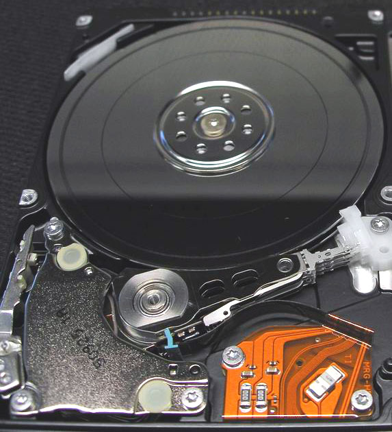
모델 : HTS726060M9AT00
증상 : 헤더손상 및 미디어 스크래치로 인한 인식장애
원인 : 충격으로 인한 1차 헤더 손상 및 전원인가로 인한
2차 미디어 손상
% 일반적으로 헤더손상 상태에서 전원인가시 미디어 상에 원형스크래치를 동반합니다.

| Developer | Apple |
|---|---|
| Full name | Hierarchical File System Plus |
| Introduced | January 19, 1998 (Mac OS 8.1) |
| Partition identifier | Apple_HFS (Apple Partition Map) 0xAF (MBR) Apple_HFSX (Apple Partition Map) when HFSX 48465300-0000-11AA- AA11-00306543ECAC (GPT) |
| Structures | |
| Directory contents | B-tree |
| File allocation | Bitmap |
| Bad blocks | B-tree |
| Limits | |
| Max file size | 8 EiB[1] |
| Max number of files | 4,294,967,295 (232-1) |
| Max filename length | 255 characters (255 UTF-16 encoding units, normalized to Apple-modified variant of Unicode Normalization Format D) |
| Max volume size | 8 EiB [2] |
| Allowed characters in filenames | Unicode, any character, including NUL. OS APIs may limit some characters for legacy reasons |
| Features | |
| Dates recorded | access, attributes modified, backed up, contents modified, created |
| Date range | January 1, 1904 - February 6, 2040 |
| Date resolution | 1 s |
| Forks | Yes |
| Attributes | Color (3 bits, all other flags 1 bit), locked, custom icon, bundle, invisible, alias, system, stationery, inited, no INIT resources, shared, desktop |
| File system permissions | Unix permissions, NFSv4 ACLs (Mac OS X v10.4 onward) |
| Transparent compression | Yes (on Mac OS X 10.6 and higher) |
| Transparent encryption | No, although per-home directory AES using HFS+ formatted .dmg volumes is possible using FileVault in Mac OS X v10.3 onward |
| Supported operating systems | Mac OS 8.1, Mac OS 9, Mac OS X, & Darwin, Linux, Microsoft Windows (through MacDrive or Bootcamp[citation needed] IFS drivers) |
HFS Plus or HFS+ is a file system developed by Apple Inc. to replace their Hierarchical File System (HFS) as the primary file system used in Macintosh computers (or other systems running Mac OS). It is also one of the formats used by the iPod digital music player. HFS Plus is also referred to as Mac OS Extended (or, erroneously, “HFS Extended”), where its predecessor, HFS, is also referred to as Mac OS Standard (or, erroneously, as “HFS Standard”). During development, Apple referred to this filesystem with the codename Sequoia.[3]
HFS Plus is an improved version of HFS, supporting much larger files (block addresses are 32-bit length instead of 16-bit) and using Unicode (instead of Mac OS Roman or any of several other character sets) for naming the items (files, folders) – names which are also character encoded in UTF-16[verification needed] and normalized to a form very nearly the same as Unicode Normalization Form D (NFD)[4] (which means that precomposed characters like are decomposed in the HFS+ filename and therefore count as two characters[5] and UTF-16 implies that characters from outside the Basic Multilingual Plane — often seldom used and characters from ancient writing systems — also count as two characters in an HFS+ filename). HFS Plus permits filenames up to 255 UTF-16 characters in length, and n-forked files similar to NTFS, though until recently, almost no software takes advantage of forks other than the data fork and resource fork. HFS Plus also uses a full 32-bit allocation mapping table, rather than HFS’s 16 bits. This was a serious limitation of HFS, meaning that no disk could support more than 65,536 allocation blocks under HFS. When disks were small, this was of little consequence, but as larger-capacity drives became available, it meant that the smallest amount of space that any file could occupy (a single allocation block) became excessively large, wasting significant amounts of space. For example, on a 1 GB disk, the allocation block size under HFS is 16 KB, so even a 1 byte file would take up 16 KB of disk space. Unlike most other file systems HFS Plus supports hard links to directories.
Like HFS, HFS Plus uses B-trees to store most volume metadata.
Contents[hide] |
HFS+ was introduced with the January 19, 1998 release of Mac OS 8.1.[1] However its first appearance, as a beta filesystem, was in the never-released Copland OS betas.
With the release of the 10.2.2 update on November 11, 2002, Apple added optional journaling features to HFS Plus for improved data reliability. These features were easily accessible in Mac OS X Server, but only accessible through the command line in the standard desktop client.[6] With Mac OS X v10.3, all HFS Plus volumes on all Macs are set to be journaled by default. Within the system, an HFS Plus volume with a journal is identified as HFSJ.
10.3 also introduced another version of HFS Plus called HFSX. HFSX volumes are almost identical to HFS Plus volumes, except that they are never surrounded by the HFS Wrapper that is typical of HFS Plus volumes and they optionally support case sensitivity for file and folder names. HFSX volumes can be recognized by two entries in the Volume Header, a value of HX in the signature field and 5 in the version field.[1]
Additionally, Mac OS X 10.3 marked Apple's adoption of Unicode 3.2 decomposition, superseding the Unicode 2.1 decomposition used previously. This change has caused problems for developers writing software for Mac OS X.[7]
With 10.4, Apple added support for Inline Attribute Data records, something that had been a part of the Mac OS X implementation of HFS Plus since at least 10.0, but always marked as "reserved for future use".[8] Until the release of Mac OS X Server 10.4, HFS Plus supported only the standard UNIX file system permissions, however 10.4 introduced support for access control list-based file security, which provides a richer mechanism to define file permissions and is also designed to be fully compatible with the file permission models on other platforms such as Microsoft Windows XP and Windows Server 2003.[9]
HFS Plus volumes are divided into sectors (called logical blocks in HFS), that are usually 512 bytes in size. These sectors are then grouped together into allocation blocks which can contain one or more sectors; the number of allocation blocks depends on the total size of the volume. HFS Plus uses a larger value to address allocation blocks than HFS, 32 bits rather than 16 bits; this means it can access 4,294,967,296 (= 232) allocation blocks rather than the 65,536 (= 216) allocation blocks available to HFS.[1]
Formerly, HFS Plus volumes were embedded inside an HFS standard filesystem. This was phased out by the Tiger transition to Intel Macs, where the HFS Plus filesystem was not embedded inside a wrapper. The wrapper was designed for two purposes; it allowed Macintosh computers without HFS Plus support in their ROM to boot HFS Plus volumes and it also was designed to help users transition to HFS Plus by including a minimal HFS volume with a read-only file called Where_have_all_my_files_gone?, explaining to users with versions of Mac OS 8.0 and earlier without HFS Plus, that the volume requires a system with HFS Plus support. The original HFS volume contains a signature and an offset to the embedded HFS Plus volume within its volume header. All allocation blocks in the HFS volume which contain the embedded volume are mapped out of the HFS allocation file as bad blocks.[1]
There are nine structures that make up a typical HFS Plus volume:[1]
The Linux kernel includes the hfsplus module[10] for mounting HFS+ filesystems. HFS+ fsck and mkfs have been ported to Linux and are part of the hfsprogs package.[11] These drivers currently have issues with corruption of HFS+ drives with a capacity greater than 2 TB. As such Linux distributions such as Ubuntu do not allow mounting of HFS+ drives or partitions greater than 2 TB.[12]
The Linux HFS+ kernel driver has support to read and write to HFS+ non-journaled drives/parititions but only has read support of journaled HFS+. Journaling ability was added to HFSplus when Mac OS X came out and is by default on for Mac OS X installations. Journaling is a redundant behavior of a filesystem that helps protect data loss. If planning to write to an HFS+ partition then drive journaling must be turned off in OSX.[13]
On Windows, a fairly complete filesystem driver for HFS+ exists as a commercial software package called MacDrive.[14] This package allows Windows users to read and write HFS+ formatted drives, and read Mac-format optical disks.
Another solution is provided by Paragon, with their HFS+ for Windows driver; this supports both read and write on HFS+ partitions.[15]
Apple has released read-only HFS+ drivers for Windows XP, Windows Vista, and Windows 7 in Boot Camp in Mac OS X 10.6. Microsoft has created a HFS+ driver for the XBox 360 mainly for the purpose of reading HFS+ formatted iPods.
A free (GPL) alternative to MacDrive is HFSExplorer written by Erik Larsson.[16] HFSExplorer is an application for viewing and extracting files from an HFS+ volume (Mac OS Extended) or an HFSX volume (Mac OS Extended, Case-sensitive) located either on a physical disk, on a .dmg disk image, or in a raw file system dump. HFSExplorer is less complete than MacDrive in the sense that it can read, but not write to HFS formatted volumes.
MBR (Master Boot Record)  MBR - Master Boot Record. MBR은 디스크의 첫번째 섹터에 있습니다. 플래시메모리에는 MBR이 없습니다. 대신 Boot sector가 있습니다. MBR 에는 해당드라이브의 파티션에 관한 정보가 저장됩니다.4개의 파티션생성이 가능하나 일반적으로 플래시메모리에는 1파티션으로만 관리하는 경우가 많습니다. boot sector 의 마직막에는 2-byte 의 signature word 또는 sector marker 55 AA가 있습니다. MBR: shift size Description  Flag Flag of boot partition 80 - boot 00 - no Type 파티션구분 FAT16 - 04, 06, 0E FAT32 - 0B, 0C NTFS - 07 확장파티션 - 0f 확장 DOS 파티션 - 05 Start 파티션의 시작주소 Size 파티션의 섹터수 |


저용량 저장매체의 경우 일반적으로 FAT 파일시스템을 적용하는 경우가 많습니다.
FAT 파일시스템의 구조를 살펴보면 아래그림과 같습니다.
MBR - Master boot record
- Boot - boot record
- FAT16 table
- FAT32 table
- Dir (for FAT16 and FAT32) 
이 밖의 모든 것들은 ext2와 같다. ext2를 유지하고 복구하기 위해 충분한 테스트를 거쳐 보다 완전해진 파일 시스템 유지보수 유틸리티들을 포함하여 ext2 파일 시스템에서 큰 변화 없이 ext3와 함께 사용될 수 있도록 하였다. ext2와 ext3 둘 다 e2fsprogs를 사용하며 이 유틸리티는 fsck를 포함하고 있다. 이러한 밀접한 관련으로 이 두 파일 시스템들은 상호 변환이 용이하다.
Ext3를 지원하는 리눅스 시스템에서는 다음과 같은 3단계 저널링을 사용할 수 있다.
두 파일 시스템의 메타 데이터와 파일 컨텐츠는 메인 파일 시스템에 전달되기 전에 저널에 기록된다. 저널은 비교적 디스크와 관련이 있어서 어떤 경우에는 성능을 향상시킬 수 있으나, 데이터가 저널에 한 번, 파일 시스템에 한 번, 이렇게 두 번 기록되기 때문에 성능이 저하될 수도 있다.
메타 데이터만 저널에 기록된다. 파일 컨텐츠는 기록되지는 않지만 만일 관련된 메타 데이터가 저널에 기록되면 파일 컨텐츠는 디스크에 반드시 기록된다. 이는 많은 리눅스 배포판에 기본 설정으로 되어 있다. 만일 파일을 읽거나 쓰는 도중에 전원이 갑자기 꺼지거나 커널 패닉 상태가 되면, 저널은 새로운 파일을 가리키게 되거나 추가된 데이터가 넘겨지지 않으며, 삭제 처리된다. 하지만, 중복 쓰기가 된 파일은 원본이 저장되지 않아 파일이 손상될 수 있는데, 파일을 복구하기 위한 충분한 정보 없이 새 파일과 이전 파일의 중간 상태에서 파일이 종료될 수 있다. - 새로운 데이터는 완벽하게 디스크에 저장되지 않으며, 이전 데이터는 어디에도 저장되지 않는다. - 심한 경우에는, 중간 상태가 이전 데이터와 새 데이터 사이에 혼란을 줄 수 있다.[1][2]
메타 데이터만 저널에 기록되며, 파일의 내용은 기록되지 않는다. 파일 내용은 저널이 업데이트된 후에나 아니면 그 이전에 기록될 수 있으며, 결과적으로 충돌 바로 전에 수정된 파일들은 손상될 수 있다. 예를 들어, 추가된 파일이 실제 크기보다 더 큰 파일로 저널에 기록되면, 결국은 "쓰레기(의미 없는 정보)"를 만들게 된다. 오래된 파일일수록 저널이 복구된 후에 예상치 못한 결과가 나타날 수 있다. 데이터와 저널 사이에 동시성이 결여되며 대부분의 경우에서 점점 심해진다. XFS와 JFS는 이러한 저널링 레벨을 사용하지만 데이터를 기록하지 않기 때문에 모든 "쓰레기"는 재부팅 시 완전히 삭제된다.
일부 상황에서는 동적 inode 할당 및 확장과 같은 현대 파일시스템의 기능 부족이 단점으로 여겨질 수 있지만, 복구의 측면에서는 이러한 사실이 아주 뛰어난 장점이 된다. 파일 시스템의 메타 데이터는 모두 수정되고, 잘 알려진 위치에 존재하며, 데이터 구조에 일부 중복성이 내재되어 있어, 트리 기반의 파일 시스템이 복구되기 어려운 상황에서도 뚜렷한 데이터 손상에도 불구하고 ext2 및 ext3 파일시스템이 복구될 수 있다.
ext3는 ext2와 대부분 호환이 가능하도록 하는 것을 목표로 하였고, 많은 on-disk 구조들이 ext2의 on-disk와 비슷하다. 이 때문에, ext3는 inode의 동적 할당 및 다양한 블록 크기(frag와 tail)와 같은 최신 파일시스템 설계의 기능들이 부족하다. ext3 파일 시스템은 쓰기를 위해 마운트 되어있는 동안에는 fsck를 할 수 없다. 읽기-쓰기가 마운트 되어있는 동안 수집된 파일 시스템의 덤프 작업은 데이터 손상을 가져올 수 있다.
ext3는 JFS, ext4, 그리고 XFS와 같은 다른 파일 시스템에서 볼 수 있는 기능인 extents 기능을 지원하지 않는다.
파일 시스템 레벨에서 사용할 수 있는 온라인 ext3 조각 모음 기능은 없다. e2defrag라고 하는 오프라인 ext2 조각 모음기가 있지만 ext3 파일 시스템은 ext2로 먼저 재변환되어야 한다. e2defrag는 데이터를 손상시킬 수 있다. 왜냐하면 e2defrag는 ext3의 새로운 기능들을 어떻게 다루어야 하는지 잘 알지 못하기 때문이다.[3]
사용자 공간에서 이용할 수 있는 defragmentation 도구에는 Shake[4]와 defrag[5] 등이 있다. Shake는 전체 파일을 위한 공간을 바로 할당하며 단편화가 많이 되지 않도록 새롭게 파일을 할당하는 역할을 한다. 또한, 다음에 같이 사용되는 파일을 서로 쓸 수 있도록 한다. Defrag는 각 파일 스스로가 복사할 수 있도록 한다. 하지만 이러한 도구들은 파일 시스템이 비어 있을 때만 작동한다. 실제 조각 모음 도구는 ext3를 위해 존재하는 것이 아니다. [6] 'Linux System Administrator Guide' 에서는 "현재의 리눅스 파일 시스템은 연속적인 섹터에 저장될 수 없음에도 불구하고 서로가 파일 상에서 근접하게 모든 블록을 최소한으로 유지함으로써 단편화를 허용한다. 따라서 리눅스 시스템에서 단편화를 걱정할 필요는 없다." 라고 기술되어 있다.[7]
전술한 것과는 상관 없이, 파일 단편화는 멀티미디어 서버 응용 프로그램에서와 같은 서버 환경에서는 매우 중요한 문제가 될 수 있다. ext3는 FAT 파일 시스템보다는 파일 단편화에 강한 편이지만 그럼에도 불구하고 ext3 파일 시스템은 시간이 지날수록 단편화가 더욱 진행된다. 결과적으로 ext3의 다음 버전인 ext4의 경우 파일 시스템 조각 모음 유틸리티를 포함하며 extents 또한 지원하게 된다. 속도가 빠르고, 동시적이며 랜덤한 파일 생성, 업데이트 및 접근이 일어나는 곳에서의 서버 응용 프로그램들은, (ext3와 같은) 일부 리눅스 파일 시스템에 조각 모음 기능이 없어서 큰 문제가 되기도 한다. 이러한 시스템에는 큰 규모의 carrier grade 음성 메일 시스템을 포함, Media-Messaging Service Centers(MMSCs) 및 SMS/SMSC(Short Message Service Centers) 서버도 포함된다. 규모가 큰 음성 메일과 같은 미디어 서버나 UMS 서버는 거의 실시간 상태로 수많은 사용자에게 음성 및 영상 스트림을 연결해주어야 한다. 이러한 타입의 응용 프로그램들은 파일 단편화가 이루어질 가능성이 있다. 음성이나 영상 파일을 재생하는 동안 미디어 파일 내에 많은 단편화 현상 때문에 접근 지연으로 재생 불능이나 재생 방해가 발생할 수 있다. 단편화 현상이 증가함에 따라, CPU 및 I/O 오버헤드 증가로 디스크 thrashing을 일으켰던 단편화를 가져오게 됨으로써 이러한 시스템들의 서비스 능력이 떨어지게 된다.
ext3의 비공식 패치에서는 투명 압축이 지원된다. 이 패치는 e2compr의 직접적인 포트이며 개발이 더 필요한 상태이며, 업스트림 커널과 컴파일 및 부팅이 잘 되지만 저널링은 아직 구현되지 않았다. 현재 패치는 e3compr이며 다음 링크에서 확인할 수 있다: http://sourceforge.net/projects/e3compr/
ext3는 개별 파일 및 전체 파일 시스템 상의 최대 크기에 제한을 두고 있다. 이러한 제한은 파일 시스템의 블록 사이즈에 따라 결정된다.[8] (다음 차트 참조)
| 블록 크기 | 파일 최대 크기 | 파일 시스템 최대 크기 |
| 1KiB | 16GiB | 2TiB |
| 2KiB | 256GiB | 8TiB |
| 4KiB | 2TiB | 16TiB |
| 8KiB | 2TiB | 32TiB |
참고 8KiB 블록 사이즈는 8KiB 페이지(Alpha와 같은)를 허용하는 아키텍처에서만 가능하다. [영문 ext3 wiki] 여기와 내용이 틀림.
Ext3는 저널에 기록할 때 checksum 검사를 하지 않는다. ‘barrier=1’이 마운트 옵션 (/etc/fstab)으로써 활성화되지 않고, 하드웨어가 캐시에 기록이 되지 않을 때, 충돌이 일어나는 동안 심각한 파일 시스템 손상의 위험을 일으킨다.[9][10] (이 옵션은 대부분 모든 유명한 리눅스 배포판에는 기본적으로 비활성화 상태로 되어 있는데 이것은 대부분의 리눅스 배포판들이 이러한 위험에 노출되어 있다는 것을 의미한다.) 다음과 같은 시나리오를 생각해 볼 수 있다. 하드 디스크 쓰기가 제대로 작동하지 않는다면 (쓰기 속도를 향상시키기 위한 하드 디스크 캐싱 때문에), 하드 디스크는 다른 관련된 블록에 쓰기가 실행되기 전에 하나의 트랜잭션의 commit 블록을 종종 쓰게 된다. 다른 블록들에 쓰기가 되기 전에 전원이 잘못되거나 커널 패닉이 발생하면, 시스템은 재부팅을 해야만 하는 상태가 된다. 리부팅 시, 파일 시스템은 정상적으로 로그를 읽어 들여와서, winners (유효한 commit 블록과 함께 표시되도록 했던 유효하지 않은 트랜잭션을 포함하여 commit 블록이 있는 트랜잭션)를 재실행한다. 종료되지 않은 디스크 쓰기는 결과적으로 진행될 것이지만 손상된 저널 데이터를 사용하게 된다. 파일 시스템은 저널을 재실행하는 동안 손상된 데이터와 함께 정상적인 데이터의 중복 쓰기를 실행한다. 만일 checksum이 사용되었더라면 (상호 checksum으로 fake winner 트랜잭션의 블록이 표시가 된다면), 파일 시스템은 보다 더 잘 알게 되고 디스크 상에서 손상된 데이터를 다시 실행할 필요가 없다.
| Ext3 | |
| 개발자 | Stephen Tweedie |
| 이름 | Third Extended File System |
| 배포 | 2001년 11월 (Linux 2.4.15) |
| 파티션 식별자 | 0x83 (MBR) EBD0A0A2-B9E5-4433-87C0-68B6B72699C7 (GPT) |
| 구조 | |
| 디렉터리 내용 | Table, h-Tree, dir_index |
| 파일 할당 | bitmap (free space), table (metadata) |
| 배드 블록 | Table |
| 제한 | |
| 최대 파일 크기 | 16GiB – 2TiB |
| 최대 파일 개수 | 파일 시스템 생성 시 다양하게 지정 가능[11] |
| 최대 파일 이름 길이 | 255 바이트 |
| 최대 볼륨 크기 | 2TiB – 32TiB |
| 파일 이름 허용 문자 | NUL 및 ‘/’를 제외한 모든 바이트 단위 문자 |
| 특징 | |
| 기록 날짜 | 수정 (mtime), 속성 수정 (ctime), 접근 (atime) |
| 날짜 표현 범위 | 1901년 12월 14일 - 2038년 1월 18일 |
| 날짜 표현 단위 | 1s |
| Forks | |
| 속성 | No-atime, append-only, synchronous-write, no-dump, h-tree (directory),
immutable, journal, secure-delete, top (directory), allow-undelete |
| 파일 시스템 권한 | Unix 권한, ACLs 및 임의의 보안 속성 (Linux 2.6 이후 버전) |
| 투명 압축 | 지원 안함 |
| 투명 암호와 | 지원 안함 (블록 장치 레벨에서 제공됨) |
| 지원 OS | Linux, BSD, Windows (IFS를 통해 지원) |
| Developer | Rémy Card |
|---|---|
| Full name | Second extended file system |
| Introduced | January 1993 (Linux) |
| Partition identifier | Apple_UNIX_SVR2 (Apple Partition Map) 0x83 (Master Boot Record) EBD0A0A2-B9E5-4433-87C0-68B6B72699C7 (GPT) |
| Structures | |
| File allocation | bitmap (free space), table (metadata) |
| Bad blocks | Table |
| Limits | |
| Max file size | 16 GB - 2 TB |
| Max number of files | 1018 |
| Max filename length | 255 bytes |
| Max volume size | 2-32 TB |
| Allowed characters in filenames | Any byte except NUL and '/' |
| Features | |
| Dates recorded | modification (mtime), attribute modification (ctime), access (atime) |
| Date range | December 14, 1901 - January 18, 2038 |
| Date resolution | 1s |
| File system permissions | POSIX |
| Transparent compression | No (Available through patches) |
| Transparent encryption | No |
| Supported operating systems | Linux, BSD, Windows (through an IFS), Mac OS X (through an IFS) |
The ext2 or second extended filesystem is a file system for the Linux kernel. It was initially designed by Rémy Card as a replacement for the extended file system (ext).
The canonical implementation of ext2 is the ext2fs filesystem driver in the Linux kernel. Other implementations (of varying quality and completeness) exist in GNU Hurd, MINIX 3, Mac OS X (third-party), Darwin (same third-party as Mac OS X but untested), some BSD kernels, in Atari MiNT, and as third-party Microsoft Windows drivers.
ext2 was the default filesystem in several Linux distributions, including Debian and Red Hat Linux, until supplanted more recently by ext3, which is almost completely compatible with ext2 and is a journaling file system. ext2 is still the filesystem of choice for flash-based storage media (such as SD cards, and USB flash drives) since its lack of a journal minimizes the number of writes and flash devices have only a limited number of write cycles. Recent kernels, however, support a journal-less mode of ext4, which would offer the same benefit along with a number of ext4-specific benefits.
Contents[hide] |
The early development of the Linux kernel was made as a cross-development under the Minix operating system. Naturally, it was obvious that the Minix file system would be used as Linux's first file system. The Minix file system was mostly free of bugs, but used 16-bit offsets internally and thus only had a maximum size limit of 64 megabytes. There was also a filename length limit of 14 characters. Because of these limitations, work began on a replacement native file system for Linux.
To ease the addition of new file systems and provide a generic file API, VFS, a virtual file system layer was added to the Linux kernel. The extended file system (ext), was released in April 1992 as the first file system using the VFS API and was included in Linux version 0.96c. The ext file system solved the two major problems in the Minix file system (maximum partition size and filename length limitation to 14 characters), and allowed 2 gigabytes of data and filenames of up to 255 characters. But it still had problems: there was no support for separate access, inode modification and data modification timestamps.
As a solution for these problems, two new filesystems were developed in January 1993: xiafs and the second extended file system (ext2), which was an overhaul of the extended file system incorporating many ideas from the Berkeley Fast File System. ext2 was also designed with extensibility in mind, with space left in many of its on-disk data structures for use by future versions.
Since then, ext2 has been a testbed for many of the new extensions to the VFS API. Features such as POSIX ACLs and extended attributes were generally implemented first on ext2 because it was relatively simple to extend and its internals were well-understood.
On Linux kernels prior to 2.6.17,[1] restrictions in the block driver mean that ext2 filesystems have a maximum file size of 2TB.
ext2 is still recommended over journaling file systems on bootable USB flash drives and other solid-state drives. ext2 performs fewer writes than ext3 since it does not need to write to the journal. As the major aging factor of a flash chip is the number of erase cycles, and as those happen frequently on writes, this increases the life span of the solid-state device.[2] Another good practice for filesystems on flash devices is the use of the noatime mount option, for the same reason.
The space in ext2 is split up into blocks. These blocks are divided into block groups, analogous to cylinder groups in the Unix File System. There are typically thousands of blocks on a large file system. Data for any given file is typically contained within a single block group where possible. This is done to reduce external fragmentation and minimize the number of disk seeks when reading a large amount of consecutive data.
Each block group contains a copy of the superblock and block group descriptor table, and all block groups contain a block bitmap, an inode bitmap, an inode table and finally the actual data blocks.
The superblock contains important information that is crucial to the booting of the operating system, thus backup copies are made in multiple block groups in the file system. However, typically only the first copy of it, which is found at the first block of the file system, is used in the booting.
The group descriptor stores the location of the block bitmap, inode bitmap and the start of the inode table for every block group and these, in turn are stored in a group descriptor table.
Every file or directory is represented by an inode. The inode includes data about the size, permission, ownership, and location on disk of the file or directory.
Example of ext2 inode structure:

Quote from the linux kernel documentation for ext2:
"There are pointers to the first 12 blocks which contain the file's data in the inode. There is a pointer to an indirect block (which contains pointers to the next set of blocks), a pointer to a doubly-indirect block (which contains pointers to indirect blocks) and a pointer to a trebly-indirect block (which contains pointers to doubly-indirect blocks)."
So, there is a structure in ext2 that has 15 pointers, the first 12 are for direct blocks. Pointer number 13 points to an indirect block, number 14 to a doubly-indirect block and number 15 to a trebly-indirect block.
Each directory is a list of directory entries. Each directory entry associates one file name with one inode number, and consists of the inode number, the length of the file name, and the actual text of the file name. To find a file, the directory is searched front-to-back for the associated filename. For reasonable directory sizes, this is fine. But for huge large directories this is inefficient, and ext3 offers a second way of storing directories that is more efficient than just a list of filenames.
The root directory is always stored in inode number two, so that the file system code can find it at mount time. Subdirectories are implemented by storing the name of the subdirectory in the name field, and the inode number of the subdirectory in the inode field. Hard links are implemented by storing the same inode number with more than one file name. Accessing the file by either name results in the same inode number, and therefore the same data.
The special directories "." and ".." are implemented by storing the names "." and ".." in the directory, and the inode number of the current and parent directories in the inode field. The only special treatment these two entries receive is that they are automatically created when any new directory is made, and they cannot be deleted.
When a new file or directory is created, the EXT2 file system must decide where to store the data. If the disk is mostly empty, then data can be stored almost anywhere. However, performance is maximized if the data is clustered with other related data to minimize seek times.
The EXT2 file system attempts to allocate each new directory in the group containing its parent directory, on the theory that accesses to parent and children directories are likely to be closely related. The EXT2 file system also attempts to place files in the same group as their directory entries, because directory accesses often lead to file accesses. However, if the group is full, then the new file or new directory is placed in some other non-full group.
The data blocks needed to store directories and files can found by looking in the data allocation bitmap. Any needed space in the inode table can be found by looking in the inode allocation bitmap.
| Block size: | 1 KB | 2 KB | 4 KB | 8 KB |
|---|---|---|---|---|
| max. file size: | 16 GB | 256 GB | 2 TB | 2 TB |
| max. filesystem size: | 4* TB | 8 TB | 16 TB | 32 TB |
The reason for some limits of the ext2-file system are the file format of the data and the operating system's kernel. Mostly these factors will be determined once when the file system is built. They depend on the block size and the ratio of the number of blocks and inodes. In Linux the block size is limited by the architecture page size.
There are also some userspace programs that can't handle files larger than 2 GB.
The maximum file size is limited to min( ((b/4)3+(b/4)2+b/4+12)*b, 232*b ) due to the i_block (an array of EXT2_N_BLOCKS) and i_blocks( 32-bits integer value ) representing the amount of b-bytes "blocks" in the file.
The limit of sublevel-directories is 31998 due to the link count limit. Directory indexing is not available in ext2, so there are performance issues for directories with a large number of files (10,000+). The theoretical limit on the number of files in a directory is 1.3 × 10²⁰, although this is not relevant for practical situations.
Note: In Linux kernel 2.4 and earlier block devices were limited to 2 TB, limiting the maximum size of a partition regardless of block size.
e2compr is a modification to the ext2 file system driver in the Linux kernel to support online compression and decompression of files on file system level without any support by user applications.
e2compr is a small patch against the ext2 file system that allows on-the-fly compression and decompression. It compresses only regular files; the administrative data (superblock, inodes, directory files etc.) are not compressed (mainly for safety reasons). Access to compressed blocks is provided for read and write operations. The compression algorithm and cluster size is specified on a per-file basis. Directories can also be marked for compression, in which case every newly created file in the directory will be automatically compressed with the same cluster size and the same algorithm that was specified for the directory.
e2compr is not a new file system. It is only a patch to the ext2 file system made to support the EXT2_COMPR_FL flag. It does not require you to make a new partition, and will continue to read or write existing ext2 file systems. One can consider it as simply a way for the read and write routines to access files that could have been created by a simple utility similar to gzip or compress. Compressed and uncompressed files coexist nicely on ext2 partitions.
The latest e2compr-branch is available for current releases of 2.6 and 2.4 Linux kernels, but development is stalled. There are also older branches for older 2.0 and 2.2 kernels, which are more stable.
exFAT (확장 파일 할당 테이블, Extended File Allocation Table, 줄여서 FAT64)는 특허 출원 중인[1]사유 파일 시스템으로, 마이크로소프트사가 윈도 CE 6.0 장치와 데스크톱 운영 체제 윈도 비스타 서비스 팩 1[2] 및 윈도 7, 그리고 자사의 서버 운영 체제인 윈도 서버 2008에 도입하기 위해 만든 것이다.[3].
exFAT는 NTFS 파일 시스템이 자료 구조 오버헤드 등의 문제로 적절치 못할 경우, 또는 이전 버전인 FAT 파일 시스템의 파일 크기/디렉터리 제약이 문제가 되는 경우에 사용될 수 있다.
윈도 XP와 윈도 서버 2003 (둘다 x86, x64) 사용자들은 마이크로소프트사로부터 업데이트를 내려받아 설치하면 exFAT 지원을 사용할 수 있다.[4] exFAT 파일 읽기를 지원하는 실험적인 오픈 소스 리눅스 커널 모듈은 현재 개발 중이다 [5]. 마이크로소프트 exFAT 드라이버로부터 라이선스 받아 전달된 클로즈드 소스의 읽기/쓰기 리눅스 드라이버는 Tuxera를 통해 구매하여 사용할 수 있다[6]
이전 파일 할당 테이블 (FAT) 파일 시스템 버전과 견주어 나아진 점은 다음과 같다:
이전 FAT 버전과 견주어 나빠진 점은 다음과 같다:
회사들은 exFAT를 사진기, 캠코더, 디지털 사진틀 등의 특정 그룹의 전자 기기에 통합할 수 있다. 다만 휴대 전화, 개인용 컴퓨터, 네트워크는 다른 가격 모델을 가진다. [11]
EFS uses symmetric key encryption in combination with public key technology to protect files. File data is being encrypted with symmetric algorithm (DESX). The key, used in symmetric encryption is called File Encryption Key (FEK). The FEK in its own turn is encrypted with a public/private key algorithm (RSA) and stored along with the file. The reason why two different algorithms are used is the speed of encryption. The performance burden of asymmetric algorithms is too much to use them for encrypting a large amount of data. Symmetric algorithms are about 1000 times faster making their suitable for encrypting of large amounts of data.
As a first setp to encrypt file, NTFS creates a log file called Efs0.log in System Volume Information folder on the same drive, as encrypted file. Then EFS aquires access CryptoAPI context. It uses Microsoft Base Cryptographic Provider 1.0 as cryptographic provider. Having the crypto context open, EFS generate File Encryption Key (FEK).
The next step is to get public/private key pair; if it does not exist at this stage (the case when EFS invoked first time), EFS generate a new pair. EFS uses 1024-bit RSA algorithm to encrypt FEK.
Then, EFS creates Data Decryption Field (DDF) for the current user, where it places FEK and encrypts it with public key. If recovery agent is defined by system policy, EFS creates also Data Recovery Field (DRF) and places there FEK encrypted with public key of recover agent. A separate DRA is created for every recovery agent defined. Please note, that on Windows XP not included into domain, there's no recovery agent is defined, so this step is omitted.
Now a temporary file Efs0.tmp is created in the same folder as the file being encrypted. The contents of original file (plain text) is copied into temporary file, after that the original is overwritten with encrypted data. By default, EFS uses DESX algorithm with 128-bit key to encrypt file data, but Windows could be also configured to use stronger 3DES algorithm with 168-bit key. In that case FIPS compliant algorithms usage must be turned on in LSA policy (it is disabled by default):

EFS uses the registry to determine if it will use DESX or 3DES. If HKLMSYSTEMCurrentControlSetControlLSAFipsAlgorithmPolicy = 1, then 3DES will be used. If not, then EFS checks HKLMSoftwareMicrosoftWindows NTCurrentVersionEFSAlgorithmID (this value may not be present); if present, it will have ID CALG_3DES or CALG_DESX, otherwise, DESX should be used.
After encryption is done, temporary and log files are deleted.

After file is encrypted, only users who has correspondent DDF or DRF can access the file. This mechanism is separate from common security meaning that beside rights to access file, the file must have its FEK encrypted with user's public key. Only user who can decrypt FEK with his own private key, can access the file. The consequence is, that user, who has access to the file, can encrypt it thus preventing the owner to access his own file. Initially only one DDF is created for user who encrypts the file, but later he can add extra users to key ring. In this case EFS simply decrypts FEK with private key of user who wants to give access to the file to another user, and encrypts FEK with public key of target user, thus creating a new DDF which is stored along with the first one.
The decryption process is opposite to encryption:

First, system checks if user has a private key used by EFS. If yes, it reads EFS attributes and walk through the DDF ring looking for DDF for current user. If DDF is found, user's private key is used to decrypt FEK extracted from DDF. Using decrypted FEK, EFS decrypts file data. It should be noticed that file never decrypted in whole but rather by sectors when upper level module requests particular sector.
Recovery process is similar to decryption, except that it uses the recovery agent's private key to decrypt the FEK in the DRF, not in DDF:

DRA policy is implemented differently for Windows 2000 and Windows XP. In Windows 2000 by default on computers, not included into domain, local Administrator is added to Public Key Policy as Encrypted Data Recovery Agent. So, when user encrypts file, both DDF and DRF fields are created. If the last DRA is deleted, the whole EFS functionality is turned off and it is not possible to encrypt file anymore.

In Windows XP the situation is different. Since majority of home users working standalone do not need anybody else to be able to decrypt file except themselves, there's no need in data recovery agents, so there's no DRA included into Public Key Policy and EFS works without DRA. In this case only DDF field is created for encrypted file.
The Encrypting File System (EFS) provides the core file encryption technology used to store encrypted files on NTFS volumes. EFS keeps files safe from intruders who might gain unauthorized physical access to sensitive, stored data (for example, by stealing a portable computer or external disk drive).
Users work with encrypted files and folders just as they do with any other files and folders. Encryption is transparent to the user who encrypted the file; the system automatically decrypts the file or folder when the user accesses. When the file is saved, encryption is reapplied. Users who are not authorized to access the encrypted files or folders transparently receive an "Access denied" message if they try to open, copy, move, or rename the encrypted file or folder. The exact message text may vary depending on application which tries to access the file, because it is related not to user rights for file but to ability of EFS to decrypt file using user's private key.
EFS has the following benefits over 3rd party encrypting applications:
Did anyone tell you that your hard disk is a pretty tricky machine? When you first installed your operating system, you may be pleased to know how smooth and efficient your software applications are running. But gradually, it slows down and this bothers you. What truly causes the dip in performance? You may argue that your disk is just a couple of months old. This has much to do with the way you operate on your system.
Try to imagine a big tool bucket filled with gadgets. Initially, the bucket only contains a few spanners, a hammer and some screws. So every time you search for a particular item, it is relatively easy to find. But soon as you keep pilling the bucket with all sorts of items and especially when the amount of items grows, you'll discover that you may need more time just to search for a particular screw head. In such cases, uninstall any unnecessary software and defragment your disk. Typically, your system performance will dip when the amount of data in your hard disk starts to grow.
Next, would you be surprised if I were to tell you that 30% of your data in your computer may be junk files? Temporary files are stocked up in your computer each time you browse the internet or perform an installation. Most programs clear these files away after it exits but unfortunately, software that are poorly written do not. Thankfully, Microsoft Windows comes with a couple of useful utilities which helps to solve some of these problems.
![]()
The disk defragmenter packs your data neatly to facilitate quick accessibility. Disk Cleanup does the job of scanning and removing all redundant temporary files. Unnecessary startup files could also be cleaned up.
And to cope with physical error such as bad sectors, ScanDisk helps to repair and recover any data lost due to mild data corruption.Your could also fix minor system file corruption or repair the corrupted system files essential for the system operation. If you suspect the installed software is giving you problems, try to repair the software corruption.
So now you see that there is more to just picking and plunging a speedy hard disk drive into your computer. Healthy and regular disk maintenance practice can greatly benefit your system and data.
Digital forensics (sometimes Digital forensic science) is a branch of forensic science encompassing the recovery and investigation of material found in digital devices, often in relation to computer crime.[1][2] The term digital forensics was originally used as a synonym for computer forensics but has expanded to cover all devices capable of storing digital data and is now used to describe the entire field.[1] The discipline evolved in a haphazard manner during the 1990s and it was not until the early 2000s that national policies were created.
Investigations can fall into four categories. The most common category is forensic analysis, where evidence is recovered to support or oppose a hypothesis before a criminal court, this is closely related to intelligence gathering, where material is intended to identify other suspects/crimes. eDiscovery is a form of discovery related to civil litigation and intrusion investigation is a specialist investigation into the nature and extent of an unauthorized network intrusion. The technical side of investigations is divided into several sub-branches; computer forensics, network forensics, database forensics and mobile device forensics. Any number of the fields may be utilised in an investigation.
As well as identifying direct evidence of a crime, digital forensics can be used to attribute evidence to specific suspects, confirm alibis or statements, determine intent, identify sources (for example, in copyright cases) or authenticate documents.[3] Investigations are much broader in scope than other areas of forensic analysis (where the usual aim is to provide answers to a series of simpler questions) often involving complex time-lines or hypothesis.[4]
The digital forensic process encompasses the seizure, forensic imaging (acquisition) and analysis of digital media. Finally producing a report of the digital evidence for the courts or an employer. Computer devices tend to store large amounts of information in cache/log files and deleted space and forensic examiners can recover this data as part of the analysis process.
Contents |

Prior to the 1980s crimes involving computers were dealt with using existing laws. The first computer crimes were recognized in the 1978 Florida Computer Crimes Act, which included legislation against the unauthorized modification or deletion of data on a computer system.[5][6] Over the next few years the range of computer crimes being committed increased, and laws were passed to deal with issues of copyright, privacy/harassment (e.g., cyber bullying, cyber stalking, and online predators) and child pornography.[7][8] It was not until the 1980s that federal laws began to incorporate computer offences. Canada was the first country to pass legislation in 1983.[6] This was followed by the US Federal Computer Fraud and Abuse Act in 1986, Australian amendments to their crimes acts in 1989 and the British Computer Abuse Act in 1990.[6][8]
The growth in computer crime during the 1980s and 1990s caused law enforcement agencies to begin establishing specialized groups, usually at the national level, to handle the technical aspects of investigations. For example, in 1984 the FBI launched a Computer Analysis and Response Team and the following year a computer crime department was set up within the British Metropolitan Police fraud squad. Besides being law enforcement professionals many of the early members of these groups were also computer hobbyists and became responsible for the fields initial research and direction.[9][10]
One of the first practical (or at least publicised) examples of digital forensics was Cliff Stoll's pursuit of hacker Markus Hess in 1986. Stoll, whose investigation made use of both computer and network forensic techniques, was not a specialised examiner.[11] Many of the earliest forensic examinations followed the same profile.[12]
Throughout the 1990s there was high demand for the these new, and basic, investigative resources. The strain on central units lead to the creation of regional, and even local, level groups to help handle the load. For example, the British National Hi-Tech Crime Unit was set up in 2001 to provide a national infrastructure for computer crime; with personnel located both centrally in London and with the various regional police forces (the unit was folded into the Serious Organised Crime Agency (SOCA) in 2006).[10]
During this period the science of digital forensics grew out of ad-hoc tools and techniques developed by these hobbyist practitioners. This is in contrast to other forensics disciplines which developed from work by the scientific community.[1][13] It was not until 1992 that the term "computer forensics" was used in academic literature (although prior to this it had been in informal use); a paper by Collier and Spaul attempted to justify this new discipline to the forensic science world.[14][15] This swift development resulted in a lack of standardization and training. In his 1995 book, "High-Technology Crime: Investigating Cases Involving Computers", K Rosenblatt wrote:[6]
Seizing, preserving, and analyzing evidence stored on a computer is the greatest forensic challenge facing law enforcement in the 1990s. Although most forensic tests, such as fingerprinting and DNA testing, are performed by specially trained experts the task of collecting and analyzing computer evidence is often assigned to patrol officers and detectives[16]
Since 2000, in response to the need for standardization, various bodies and agencies have published guidelines for digital forensics. The Scientific Working Group on Digital Evidence (SWGDE) produced a 2002 paper, "Best practices for Computer Forensics", this was followed, in 2005, by the publication of an ISO standard (ISO 17025, General requirements for the competence of testing and calibration laboratories).[17][6][18] A European lead international treaty, the Convention on Cybercrime, came into force in 2004 with the aim of reconciling national computer crime laws, investigative techniques and international co-operation. The treaty has been signed by 43 nations (including the US, Canada, Japan, South Africa, UK and other European nations) and ratified by 16.
The issue of training also received attention. Commercial companies (often forensic software developers) began to offer certification programs and digital forensic analysis was included as a topic at the UK specialist investigator training facility, Centrex.[6][10]
Since the late 1990s mobile devices have become more widely available, advancing beyond simple communication devices, and have been found to be be rich forms of information, even for crime not traditionally associated with digital forensics.[19] Despite this, digital analysis of phones has lagged behind traditional computer media, largely due to problems over the proprietary nature of devices.[20]
Focus has also shifted onto internet crime, particularly the risk of cyber warfare and cyberterrorism. A February 2010 report by the U.S. Joint Forces Command concluded:
Through cyberspace, enemies will target industry, academia, government, as well as the military in the air, land, maritime, and space domains. In much the same way that airpower transformed the battlefield of World War II, cyberspace has fractured the physical barriers that shield a nation from attacks on its commerce and communication.[21]
The field of digital forensics still faces outstanding issues. A 2009 paper, "Digital Forensic Research: The Good, the Bad and the Unaddressed", by Peterson and Shenoi identified a bias towards Windows operating systems in digital forensics research.[22] In 2010 Simson Garfinkel identified issues facing digital investigations in the future; including the increasing size of digital media, the wide availability of encryption to consumers, a growing variety of operating systems and file formats, an increasing number of individuals owning multiple devices and legal limitations on investigators. The paper also identified continued training issues, as well as the prohibitively high cost of entering the field.[11]
During the 1980s very few specialised digital forensic tools existed and investigators often performed live analysis on media, examining computers from within the operating system using existing sysadmin tools to extract evidence. This risked modifying data on the disk (inadvertently or otherwise) leading to claims of evidence tampering. In the early 1990s a number of tools were created to allow investigations to take place without the risk of altering data.
The need for such software was first recognised in 1989 at the Federal Law Enforcement Training Center, resulting in the creation of IMDUMP (by Michael White) and in 1990, SafeBack (developed by Sydex). Similar pieces of software were produced in other countries; DIBS (a hardware and software solution) was released commercially in the UK in 1991 and Rob McKemmish released Fixed Disk Image free to Australian law enforcement.[9] These tools allowed examiners to create an exact copy of a piece of digital media to work on; leaving the original disk intact for verification. By the end of the 90s, as demand for digital evidence grew more advanced, commercial tools (EnCase, FTK, etc.) were developed that allowed analysts to examine copies of media without using any live forensics.[6]
More recently the same progression of tool development has occurred for mobile devices; initially investigators accessed data directly on the device, these were soon replaced with specialist tools (such as XRY or Radio Tactics Aceso).[6]

A digital forensic investigation commonly consists of 3 stages; acquisition or imaging of exhibits, analysis and reporting.[6][23] Acquisition involves creating an exact sector level duplicate (or "forensic duplicate") of the media, often using a write blocking device to prevent modification of the original. Both acquired image and original media are hashed (using SHA-1 or MD5) and the values compared to verify the copy is accurate.[24]
During the analysis phase an investigators recover evidence material using a number of different methodologies and tools. In 2002 and article in the International Journal of Digital Evidence referred to this step as "an in-depth systematic search of evidence related to the suspected crime".[1] In 2006, forensics researcher Brian Carrie described an "intuitive procedure" in which obvious evidence is first identified and then "exhaustive searches are conducted to start filling in the holes."[4]
The actual process of analysis can vary between investigations, but common methodologies include conducting keyword searches across the digital media (within files as well as unallocated and slack space), recovering deleted files and extraction of registry information (for example to list user accounts, or attached USB devices).
Once evidence is recovered it is analysed to reconstruct events or actions and to reach conclusions, work that can often be performed by less specialist staff.[1] When an investigation is complete the data is presented, usually in the form of a written report, in lay persons terms.[1]
Investigations can take one of four forms. Firstly as a forensic examination, traditionally associated with criminal law, where evidence is collected to support or oppose a hypothesis. Like other areas of forensics this is often part of a wider investigation spanning a number of disciplines. A related form is "intelligence gathering", functionally identical to a forensic examination the digital evidence is intended to be used as intelligence to (for example) locate, identify or halt other crimes. As a result intelligence gathering is sometimes held to a less strict forensic standard.
In civil litigation or corporate matters the process is referred to as electronic discovery (or eDiscovery). The forensic procedure is similar to that used in criminal investigations but with different legal requirements and limitations. Finally, intrusion investigation is a specialist examination into the nature and extent of an unauthorized network intrusion. Intrusion analysis is usually performed as a damage limitation exercise after an attack, both to establish the extent of any intrusion and to try and identify the attacker.[4][3] Such attacks were commonly conducted over phone lines during the 1980s, but in the modern era are usually propagated over the internet.[25]
The main use of digital forensics is to recover objective evidence of a criminal activity (termed actus reus in legal parlance). However the diverse range of data held in digital devices can help with other areas of investigation.[3]
One major limitation to a forensic investigation is the use of encryption; this disrupts initial examination where pertinent evidence might be located using keywords. Laws to compel individuals to disclose encryption keys are still relatively new and controversial.[11]
The examination of digital media is covered by national and international legislation. For civil investigations, in particular, laws may restrict the abilities of analysts to undertake examinations. Restrictions against network monitoring, or reading of personal communications often exist.[26] For criminal investigation, national laws restrict how much information can be seized.[26] For example, in the United Kingdom seizure of evidence by law enforcement is governed by the PACE act.[6] The "International Organization on Computer Evidence" (IOCE) is one agency that works to establish compatible international standards for the seizure of evidence.[27]
In the UK the same laws covering computer crime can also affect forensic investigators. The 1990 computer misuse act legislates against unauthorised access to computer material; this is a particular concern for civil investigators who have more limitations than law enforcement.
An individuals right to privacy is one area of digital forensics which is still largely undecided by courts. The US Electronic Communications Privacy Act places limitations on the ability of law enforcement or civil investigators to intercept and access evidence. The act makes a distinction between stored communication (e.g. email archives) and transmitted communication (such as VOIP). The latter, being considered more of a privacy invasion, is harder to obtain a warrant for.[6][16] The ECPA also affects the ability of companies to investigate the computers and communications of their employees, an aspect that is still under debate as to the extent to which a company can perform such monitoring.[6]
In Europe Article 5 of the European Convention on Human Rights asserts similar privacy limitations to the ECPA. In addition it also limits the processing and sharing of personal data both within the EU and with external countries. In the UK the ability of law enforcement to conduct digital forensics investigations is legislated by the Regulation of Investigatory Powers Act.[6]

Where it will be used in a court of law, digital evidence falls under the same legal guidelines as other forms of evidence, courts do not usually require more stringent guidelines.[6][28] In the United States the Federal Rules of Evidence are used to evaluate the admissibility of digital evidence, the United Kingdom PACE and Civil Evidence acts have similar guidelines and many other countries have their own laws. US federal laws restrict seizures to items with only obvious evidential value. This is acknowledged as not always being possible to establish with digital media prior to an examination.[26]
Laws dealing with digital evidence refer to two considerations; integrity and authenticity. Integrity is ensuring that the act of seizing and acquiring digital media does not modify the evidence (either the original or the copy). Authenticity refers to the ability to confirm the integrity of information; for example that the imaged media matches the original evidence.[26] The ease with which digital media can be modified means that documenting the chain of custody from the crime scene, through analysis and, ultimately, to the court, (a form of audit trail) is important to establish the authenticity of evidence.[6]
Attorneys have argued that because digital evidence can theoretically be altered it undermines the reliability of the evidence. US judges are beginning to reject this theory, in the case US v. Bonallo the court ruled that "the fact that it is possible to alter data contained in a computer is plainly insufficient to establish untrustworthiness".[6][29] In the United Kingdom guidelines such as those issued by ACPO are followed to help document the authenticity and integrity of evidence.
Digital investigators, particularly in criminal investigations, have to ensure that conclusions are based upon factual evidence and their own expert knowledge.[6] In the US, for example, Federal Rules of Evidence state that a qualified expert may testify “in the form of an opinion or otherwise” so long as:
(1) the testimony is based upon sufficient facts or data, (2) the testimony is the product of reliable principles and methods, and (3) the witness has applied the principles and methods reliably to the facts of the case.[30]
Many of the sub-branches of digital forensics have their own specific guidelines for handling and investigating evidence. For example, mobile phones are often acquired inside a Faraday shield to stop radio traffic to the device. Or, in the UK forensic examination of computers in criminal matters is subject to ACPO guidelines.[6]
Digital forensics includes several sub-branches relating to the investigation of various types of devices, media or artefacts.
The goal of computer forensics is to explain the current state of a digital artifact; such as a computer system, storage medium or electronic document.[31] The discipline usually covers computers, embedded systems (digital devices with rudimentary computing power and onboard memory) and static memory (such as USB pen drives).
Computer forensics can deal with a broad range of information; from logs (such as internet history) through to the actual files on the drive. In 2007 prosecutors used a spreadsheet recovered from the computer of Joseph E. Duncan III to show premeditation and secure the death penalty.[3] Sharon Lopatka's killer was identified in 2006 after email messages from him detailing torture and death fantasies were found on her computer.[6]

Mobile device forensics is a sub-branch of digital forensics relating to recovery of digital evidence or data from a mobile device. It differs from Computer forensics in that a mobile device will have an inbuilt communication system (e.g. GSM) and, usually, proprietary storage mechanisms. Investigations usually focus on simple data such as call data and communications (SMS/Email) rather than in-depth recovery of deleted data.[6][32] SMS data from a mobile device investigation helped to exonerate Patrick Lumumba in the murder of Meredith Kercher.[3]
Mobile devices are also useful for providing location information; either from inbuilt gps/location tracking or via cell site logs (which track the devices within their range). Such information was used to track down the kidnappers of Thomas Onofri in 2006.[3]
Network forensics relates to the monitoring and analysis of computer network (both local network and WAN/internet) traffic for the purposes of information gathering, legal evidence or intrusion detection.[33] Traffic is intercepted (usually at the packet level) and either stored for later analysis with specialist tools or filtered in real time for relevant information. Unlike other areas of digital forensics, network data is often volatile and seldom logged, making the discipline often reactionary.
In 2000, the FBI lured computer hackers Aleksey Ivanov and Gorshkov to the United States for a fake job interview. By monitoring network traffic from the pair's computers, the FBI identified passwords that let it collect evidence directly from Russia-based computers.[6][34]
Database forensics is a branch of digital forensics relating to the forensic study of databases and their metadata.[35] Investigations use database contents, log files and in-RAM data in order to build a time-line or recover relevant information.
| Look up digital forensics in Wiktionary, the free dictionary. |
| Wikibooks has more on the topic of |
NTFS is a recoverable file system that guarantees the consistency of the volume by using standard transaction logging and recovery techniques. In the event of a disk failure, NTFS restores consistency by running a recovery procedure that accesses information stored in a log file. The NTFS recovery procedure is exact, guaranteeing that the volume is restored to a consistent state. Transaction logging requires a very small amount of overhead.
NTFS ensures the integrity of all NTFS volumes by automatically performing HDD recovery operations the first time a program accesses an NTFS volume after the computer is restarted following a failure.
NTFS also uses a technique called cluster remapping to minimize the effects of a bad sector on an NTFS volume.
Important
If either the master boot record (MBR) or boot sector is corrupted, you might not be able to access data on the volume.
NTFS views each I/O operation that modifies a system file on the NTFS volume as a transaction, and manages each one as an integral unit. Once started, the transaction is either completed or, in the event of a disk failure, rolled back (such as when the NTFS volume is returned to the state it was in before the transaction was initiated).
To ensure that a transaction can be completed or rolled back, NTFS records the suboperations of a transaction in a log file before they are written to the disk. When a complete transaction is recorded in the log file, NTFS performs the suboperations of the transaction on the volume cache. After NTFS updates the cache, it commits the transaction by recording in the log file that the entire transaction is complete.
Once a transaction is committed, NTFS ensures that the entire transaction appears on the volume, even if the disk fails. During recovery operations, NTFS redoes each committed transaction found in the log file. Then NTFS locates the transactions in the log file that were not committed at the time of the system failure and undoes each transaction suboperation recorded in the log file. Incomplete modifications to the volume are prohibited.
NTFS uses the Log File service to log all redo and undo information for a transaction. NTFS uses the redo information to repeat the transaction. The undo information enables NTFS to undo transactions that are not complete or that have an error.
Important
NTFS uses transaction logging and recovery to guarantee that the volume structure is not corrupted. For this reason, all system files remain accessible after a system failure. However, user data can be lost because of a system failure or a bad sector.
In the event of a bad-sector error, NTFS implements a recovery technique called cluster remapping. When Windows 2000 detects a bad-sector, NTFS dynamically remaps the cluster containing the bad sector and allocates a new cluster for the data. If the error occurred during a read, NTFS returns a read error to the calling program, and the data is lost. If the error occurs during a write, NTFS writes the data to the new cluster, and no data is lost.
NTFS puts the address of the cluster containing the bad sector in its bad cluster file so the bad sector is not reused.
Important
Cluster remapping is not a backup alternative. Once errors are detected, the disk should be monitored closely and replaced if the defect list grows. This type of error is displayed in the Event Log.
The set of AT Attachment standards consists of this standard and the ATA implementation standards described in ATA8-AAM. The AT Attachment ATA Command Set (ATA8-ACS) specifies the command set host systems use to access storage devices. It provides a common command set for systems manufacturers, system integrators, software suppliers, and suppliers of intelligent storage devices.
This is the seventh ATA/ATAPI standard. Released in 2003.
This standard specifies the AT Attachment Interface between host systems and storage devices. It provides a common attachment interface for systems manufacturers, system integrators, software suppliers, and suppliers of intelligent storage devices.
The application environment for the AT Attachment Interface is any host system that has storage devices contained within the processor enclosure.
Volume 1 defines the register delivered commands used by devices implementing the standard.
Volume 2 defines the connectors and cables for physical interconnection between host and storage device, the electrical and logical characteristics of the interconnecting signals, and the protocols for the transporting commands, data, and status over the interface for the parallel interface.
Volume 3 defines the connectors and cables for physical interconnection between host and storage device, the electrical and logical characteristics of the interconnecting signals, and the protocols for the transporting commands, data, and status over the interface for the serial interface.
This is the sixth ATA/ATAPI standard. Released in 2001.
This standard specifies the AT Attachment Interface between host systems and storage devices. It provides a common attachment interface for systems manufacturers, system integrators, software suppliers, and suppliers of intelligent storage devices.
The application environment for the AT Attachment Interface is any host system that has storage devices contained within the processor enclosure.
This standard defines the connectors and cables for physical interconnection between host and storage device, as well as the electrical and logical characteristics of the interconnecting signals. It also defines the operational registers within the storage device, and the commands and protocols for the operation of the storage device.
This standard maintains a high degree of compatibility with the AT Attachment with Packet Interface - 5 standard (ATA/ATAPI-5), NCITS 340-2000, and while providing additional functions, is not intended to require changes to presently installed devices or existing software.
This is the fifth ATA/ATAPI standard. Released in 2000.
This standard specifies the AT Attachment Interface between host systems and storage devices. It provides a common attachment interface for systems manufacturers, system integrators, software suppliers, and suppliers of intelligent storage devices.
The application environment for the AT Attachment Interface is any host system that has storage devices contained within the processor enclosure.
This standard defines the connectors and cables for physical interconnection between host and storage device, as well as, the electrical and logical characteristics of the interconnecting signals. It also defines the operational registers within the storage device, and the commands and protocols for the operation of the storage device.
This standard maintains a high degree of compatibility with the AT Attachment with Packet Interface Extensions standard (ATA/ATAPI-4), NCITS 317-1998, and while providing additional functions, is not intended to require changes to presently installed devices or existing software.
